Advertisement
Advertisement
Table of Contents

Summary of Contents for Yamaha XS250
-
Page 1: Power Amplifier
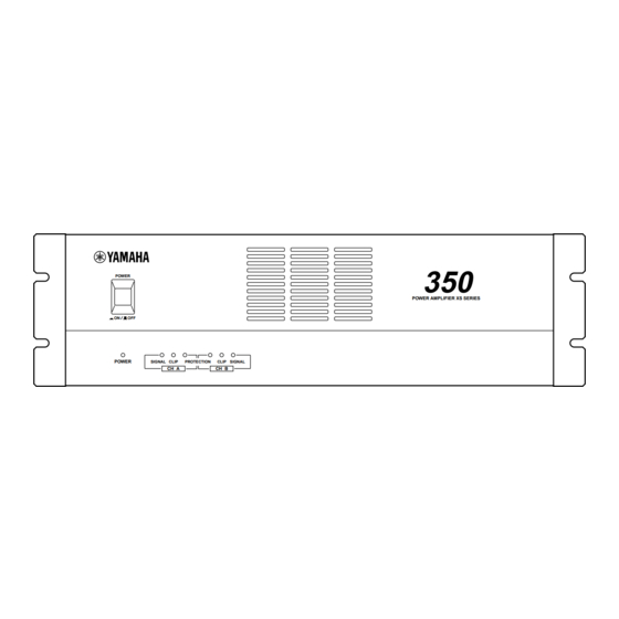
POWER AMPLIFIER XS350 XS250 Owner’s Manual POWER POWER SIGNAL CLIP PROTECTION CH A CLIP SIGNAL CH B POWER AMPLIFIER XS SERIES... - Page 2 • Variable-speed low-noise fan(s) ensures high reliability even under demanding conditions. This owner's manual covers the two models XS350, XS250. In order to take full advantage of your power amp and enjoy long and trouble-free operation, please read this owner's manual carefully before use.
-
Page 3: Table Of Contents
Precautions • Connect this unit’s power cord only to an AC outlet of the type stated in this Owner’s Manual or as marked on the unit. Failure to do so is a fire and electrical shock hazard. • Do not allow water to enter this unit or allow the unit to become wet. -
Page 4: Controls And Functions
Controls and Functions Front Panel POWER switch and indicator This is the main POWER switch. Press to power ON the amplifier. Press again to power OFF. The POWER indicator lights up when the amplifier is powered ON. SIGNAL indicators These green LED indicators light up when the respective channel’s output signal exceeds 2 Vrms. -
Page 5: Rear Panel
Rear Panel FILTER CHANNEL B CHANNEL A FREQ. FREQ. –dB CHANNEL B CHANNEL A LOW CUT LOW CUT MODE SUB WOOFER SUB WOOFER BRIDGE STEREO PARALLEL INPUT CHANNEL B CHANNEL A CHANNEL B (BRIDGE) (PARALLEL) Frequency controls/Filter select switches (CHAN- NEL A, B) These knobs and sliding switches are used to select a filter type and control the cut-off frequencies respec-... - Page 6 SPEAKERS terminals Two types of speaker output terminals: Binding post (Channel A-1, B-1) and barrier strip (Channel A-2, B-2) are available. These parallel wirings are internally connected and output identical signals simultaneously. The output impedance varies depending on whether you use either or both types of SPEAKERS terminals.
-
Page 7: Speaker Impedance
Speaker Impedance In STEREO and PARALLEL modes, the minimum load (i.e., speaker) impedance is 4 . In BRIDGE mode it is 8 . Make sure that the impedance does not fall below this specified impedance. Using the barrier strip and binding posts simultanuously STEREO mode connections: PARALLEL mode connections: BRIDGE mode connections:... - Page 8 Using the barrier strip or terminal posts STEREO mode connections: PARALLEL mode connections: • Using the barrier strip SPEAKERS – – – – Each speaker min. 4 BRIDGE mode connections: • Using the barrier strip SPEAKERS – – – Speaker min.
-
Page 9: Caution For Speaker Connection
The output capacity of your amplifier is very high: 170 W+170 W (8 ), 250 W+250 W (4 ) in stereo and 500 W (8 ) in monaural on the XS250; 230 W+230 W (8 ), 350 W+350 W (4 ) in stereo and 700 W (8 ) in monaural on the XS350. -
Page 10: Rack Mounting
The figure on the left below shows an example of a fan kit (panels and two fans) on the top slot of the rack. The fans are Minebia 3115PS-12T-B30 (with 0.9 m The figure on the right below is a dimensional diagram of a panel on which two 3115PS-12T-B30 are installed. Fan kit XS350/XS250 Blanking panel XS350/XS250 Blanking panel XS350/XS250 O or more maximum static pressure. -
Page 11: Portable Rack Mounting
Portable Rack Mounting This unit uses a forced cooling system in which air comes in through the front opening and goes out from the sides and rear. If you mount a single unit on a portable rack, be sure to maintain vent openings on the rear and sides. (Side View) Front Air intake... -
Page 12: General Specifications
Power Consumption Dimensions (W x H x D) Weight 0 dB=0.775 Vrms, Half Power=1/2 Power Output Level (Rated Power) Specifications subject to change without notice. XS250 8 /STEREO 170 W + 170 W 4 /STEREO 250 W + 250 W... -
Page 13: Block Diagram
Block Diagram INPUT CHANNEL A (BRIDGE) (PARALLEL) CHANNEL A – (BRIDGE) (PARALLEL) INPUT – CHANNEL B INPUT CHANNEL B PARALLEL BRIDGE STEREO MODE Dimensions CHANNEL A LOW CUT SUB WOOFER CHANNEL B LOW CUT SUB WOOFER W:480 CLIP SIGNAL – –... -
Page 14: Troubleshooting
8 (bridge). Check the amplifier ventilation conditions and take appropriate measures to improve airflow around the amplifier. Consult your dealer or nearest Yamaha service center. Remedy Protection Circuit The PC limiter circuit operates to protect the power transistors. The thermal protection... - Page 15 YAMAHA CORPORATION V352950 R1 1 IP 16 Pro Audio Division, #18/3 P.O. Box 3, Hamamatsu, 430-8651, Japan NP Printed in Taiwan...


