Sign In
Upload
Manuals
Brands
Siemens Manuals
Media Converter
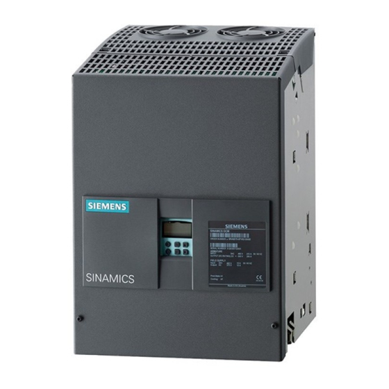
SINAMICS DCM 6RA80
Siemens SINAMICS DCM 6RA80 Manuals
Manuals and User Guides for Siemens SINAMICS DCM 6RA80. We have
1
Siemens SINAMICS DCM 6RA80 manual available for free PDF download: Faq
Siemens SINAMICS DCM 6RA80 Faq (80 pages)
Brand:
Siemens
| Category:
Media Converter
| Size: 0.86 MB
Table of Contents
Faq
1
Warning
1
CUD (Control Unit DC)
2
Second CUD
2
Basic Operating Panel Bop20/Advanced Operating Panel AOP30
2
Memory Card
2
Access Level for the BOP20
3
Restoring the Factory Settings
3
Saving the Parameters to the ROM (Non-Volatile Memory)
3
When Power-Up Is Interrupted with Display Value 33 on BOP20
3
Device Data and Device Standards
4
Motor-Related Data
4
Operating the 4Q Device as a 2Q Device
4
The Function Block Diagrams
5
Connectors and Binectors: BICO
5
Normalization of the Closed-Loop Controller Signals
6
Armature Circuit/Field Circuit
6
Fixed Values
6
Free Function Blocks
6
Drive Control Chart, DCC
7
Procedure for Assigning Parameters
7
The Operating State of the Device
7
Operation Via Bus (USS or PROFIBUS or PROFINET)
7
Controlling Via Binary Signals of Converter/Via Control Word 1 (CW1)
8
OFF2, Voltage Enable
8
OFF3, Fast Stop
8
Priority of Control Signals
9
Controller Structure for OFF1 and OFF3
9
Setpoint Value Specification
9
Main Contactor Control Terminal 109/110
10
E-Stop, Terminal 105/106
10
Brake Control
10
Automatic Restart
10
Diagnostic Memory
11
Trend Recorder Function
11
Thyristor Test with P50830
11
Faults/Alarms
11
Diagnostics for some Fault/Alarm Messages
12
F60004 Occurs
12
Field Fault
12
F60005 Occurs
12
F60105 Occurs
13
Undervoltage of Armature/Field Occurs
13
F60006 Occurs
13
F60042 Occurs
13
F60043 Occurs
14
F60167 or A60166 Occurs
14
As Soon as the Voltage Is Applied to the Power Section, a Fuse Blows
14
Fuse Tripping of the Armature Infeed Occurs Sporadically
15
Irregular Speed
15
Drive Vibrates Mechanically at a Particular Speed
15
Irregular Current
15
Module Replacement
16
Motor Speed Oscillates When Stopping in the Opposite Direction Via
16
Motor Does Not Reach Voltage
16
Motor Turns Several Percent too Slowly When an Analog Tachometer Used
16
Replacing a Device
17
Distribution of Functions to the Modules in the SINAMICS DCM
17
Power Interface Module
18
Field Module
18
Power Unit 15 and 30 a Devices
18
Controller Structure of the SINAMICS DCM
19
Allocation Board
19
Surge Absorbing Capacitor Circuit
19
The Structure of the Controller for the Armature Circuit
19
Speed Controller
20
Speed Controller Pre-Control
20
Torque Calculation
21
Current Setpoint Integrator / Reduced Gearbox Stressing
21
Actual Value of Current
21
Current Control Loop
21
Gating Unit
23
Firing Angle Limits
23
Command Stage
24
Limits
24
Controller Structure for the Field Circuit
24
EMF Control Loop
24
Optimizing the Controller with Optimization Runs
25
Field Current Setpoint Limitation
25
Actual Value for Field Current
25
Field Current Control Loop
25
Manual Controller Optimization Using the Square-Wave Generator
26
Setpoint Step Change for the Speed Controller
27
Referencemodel
28
Open-Loop Controlled Operation
29
Fundamentals of Line-Commuted Converters
31
Requirements of the Supply System
31
Three-Phase System
31
Converter for Armature Supply
32
Using a Fully Controlled Three-Phase Bridge Connection
32
B6C Connection (6RA80..-..S22-0AA0)
32
Connection (B6)A(B6)C (6RA80..-..V62-0AA0)
32
Formulas
34
Firing Angle Alpha in Degree
35
Relations between Various Operating Points of the Motor
36
Example 3 Phase Supply
36
Measurement of Current Characteristic of Line-Side Current
38
The Armature Converter in the Single-Phase Mode
39
Relationships for some Operating Points of the Motor
39
Example for Single-Phase Operation
39
Current Converter for Field Supply
40
2Q Field Infeed (Option L11)
40
Control Characteristic/Two-Pulse Half-Controlled Bridge B2Hz
41
Voltage and Current Characteristic, Circuit B2Hz
41
Measurement with Current Probe
41
Measurements that Can be Performed on the SINAMICS DCM
42
Voltage and Current Characteristic, Circuit B2C
42
Measurement of Electrical Variables
42
Measuring the Resistance of Power Semi-Conductors
43
Measurement at the Diode
44
Measurement at Thyristor Gate
44
Measurement of the Firing Pulses
44
Measurements with the Trace-Function of STARTER
45
Line to Line Voltage Armature Circuit 1U1/1V1/1W1
45
Line to Line Voltage Field Supply 3U1/3W1: R52950[3]
45
Field Current: R52952[1], Blue; Field Voltage 3C/3D, R52951[1], Orange
45
Armature Current Measurement by Two Current Transformer on Input
46
Armature Voltage 1C1/1D1
46
Testing the Current Converter Without Load
47
Testing the Current Converter with a Short-Circuited Output
47
Additional Components on the DC Converter
48
Protection with Fuses
48
Commutation Reactor, Catalog D23.1
48
RFI Suppression Filter
49
Reactive-Power Compensation, Series-Resonant Circuits for Harmonics
49
Line-Side Overvoltage Protection 7VV3002
49
Direct-Voltage-Side Overvoltage Protection, SIOV, or 7VV3003...
50
Converter Transformer
50
Converter Commutation Protector, CCP
50
High-Speed DC Circuit-Breaker/Main Contactor in the 6RA80 Infeed
50
Retrofitting an Old Current Converter by Implementing SINAMICS DCM
51
The Separately Excited Direct Current Motor
52
EMF (Electromotive Force)
53
Motor Flux Ф
53
Field Current
53
The Motor Torque
53
Relationship
54
Protection of the Motor Winding from Overtemperature
54
The Gearing
55
Example of a Motor Power Plate / Rating Plate
55
Operation
56
Maintenance
56
Sinamics DCM
56
DC Motor
57
Measurements on the Motor
58
Precautions When Operating the SINAMICS DCM on an Old Motor
58
Special Applications of the SINAMICS DCM
59
Operation of a Permanent-Magnet DC Motor
59
Input of a High Inductance Via SINAMICS DCM
59
DC Link Infeed from Pulse-Controlled Converters through SINAMICS DCM
59
A Little Control Engineering (for those Who Are Interested)
60
Time Equation and Frequency Response
60
Frequency Response and Transfer Function
60
Proportional Transfer Element
61
First-Order Lag Element
61
Transfer Element with Dead Time
62
Integral-Action Transfer Element
62
Proportional-Plus-Integral Controller; PI Controller
62
Proportional-Plus-Integral-Plus-Derivative Controller, PID-Controller
63
Controller Optimization
63
Optimization of PI Controller According to the Absolute Value Optimum
64
Optimization of the PI Controller According to the Symmetrical Optimum
65
Setpoint Smoothing
65
Comparison of the Absolute Value Optimum and Symmetrical Optimum
66
Adjustment According to the Symmetrical Optimum
67
Equivalent Time Constant of the Optimized Control Loop
67
Avoiding Overshooting of Controlled Variable in Overdriven Controller
68
Overview Tables for Optimization
68
Compensation of Disturbance Variables
69
Calculation of the Controller Parameters
69
Structure Diagram of the Entire Armature Control Loop with an Example
70
Speed Control with an Oscillating Mechanical System
71
Adaptation of the Controllers
72
Technological Controls with the SINAMICS DCM
73
Current / Torque Limitation Control
73
Master-Slave Switchover
73
Load Sharing Control
73
Load Sharing Via the Droop Function of the Speed Controller
74
Axial Winder
74
Tension Control with Constant Roll Diameter
74
Machine Tool Drives
75
Angular Synchronous Control
75
Cross-Cutter/Shear Control
75
Technology Control for Hoisting Gear Applications
75
Index
77
Advertisement
Advertisement
Related Products
Siemens DRIVE-CLiQ
Siemens SINAMICS G150
Siemens SINAMICS G130
Siemens sinamics dcp
Siemens SINAMICS G12
Siemens SINAMICS G120C DP
Siemens SINAMICS G120C PN
Siemens SINAMICS S110
Siemens SINAMICS G120XA
Siemens SINAMICS G120X
Siemens Categories
Industrial Equipment
Controller
Control Unit
Oven
Washer
More Siemens Manuals
Login
Sign In
OR
Sign in with Facebook
Sign in with Google
Upload manual
Upload from disk
Upload from URL