Sign In
Upload
Manuals
Brands
Siemens Manuals
Media Converter
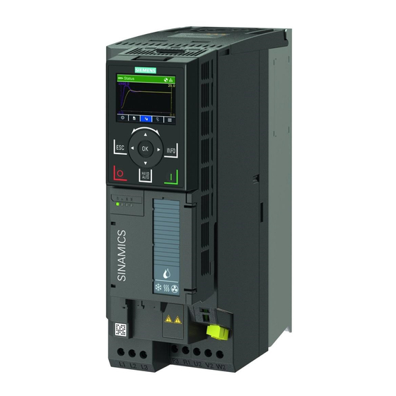
SINAMICS G120XA
User Manuals: Siemens SINAMICS G120XA Converter
Manuals and User Guides for Siemens SINAMICS G120XA Converter. We have
1
Siemens SINAMICS G120XA Converter manual available for free PDF download: Operating Instructions Manual
Siemens SINAMICS G120XA Operating Instructions Manual (919 pages)
Brand:
Siemens
| Category:
Media Converter
| Size: 13.89 MB
Table of Contents
Contents
3
Legal Information
4
Proper Use of Siemens Products
4
Qualified Personnel
4
Warning Notice System
4
Table of Contents
5
1 Fundamental Safety Instructions
13
General Safety Instructions
13
Equipment Damage Due to Electric Fields or Electrostatic Discharge
19
Warranty and Liability for Application Examples
20
Industrial Security
21
Residual Risks of Power Drive Systems
23
2 Description
25
About the Manual
25
What Is the Meaning of the Symbols in the Manual?
25
Who Requires the Operating Instructions and What For?
25
About the Converter
26
Use for the Intended Purpose
26
Use of Openssl
26
Use of Third-Party Products
26
Scope of Delivery
27
3-Phase 380 V AC to 440 V AC
28
Technical Data
28
Rating Plate
29
Directives and Standards
30
Relevant Directives and Standards
30
Standards that Are Not Relevant
31
Device Disposal
32
Recycling and Disposal
32
Optional Components
33
Overview
33
Article Number
34
Output Reactor
34
Requirements for Line Reactors
34
Sine-Wave Filter
36
Special Restrictions for Converter FSG
36
DV/Dt Filter Plus VPL
37
Operator Panel
37
Shield Connection Kit for the Power Module (FSD to FSG)
38
SINAMICS G120 Smart Access
38
Motors and Multi-Motor Drives that Can be Operated
39
Multi-Motor Operation
39
Siemens Motors that Can be Operated
39
Third-Party Motors that Can be Operated
39
3 Mounting
41
EMC-Compliant Setup of the Machine or Plant
41
EMC Zones
41
Inside the Control Cabinet
41
Control Cabinet Assembly
42
Measures Required for Several Control Cabinets
42
Control Cabinet
42
Cables
43
Cables with a High Level of Interference
43
Cables with a Low Level of Interference
43
Cable Routing Inside the Cabinet
44
Routing Converter Cables Inside and Outside a Control Cabinet
44
Routing Cables Outside the Control Cabinet
45
Requirements Relating to Shielded Cables
45
Electromechanical Components
45
Surge Voltage Protection Circuit
45
Power Losses and Air Cooling Requirements
46
Measures in Order to Ensure that the Components Are Adequately Cooled
46
Mounting the Converter
47
Basic Installation Rules
47
Requirements
47
Protection against the Spread of Fire
48
Mounting Position
48
Dimension Drawings and Drill Patterns
49
Dimensions and Clearance Distances (MM)
49
Drill Patterns (MM)
50
Mounting the Shield Connection Kit
51
Mounting the Shield Connection Kit for the Control Unit
51
FSH and FSJ
51
Mounting the Shield Connection Kit for the Power Module, FSA ... FSC
52
Mounting the Shield Connection Kit for the Power Module, FSD ... FSG
52
Procedure, FSD/FSE
53
Procedure, FSF
53
Procedure, FSG
54
Additional Mounting Instructions, FSD ... FSG
54
Hoisting Gear
54
Additional Mounting Instructions, FSH/FSJ
55
Lifting the Converter
55
Removing the Pallet
56
Lifting the Converter into the Cabinet
56
Mounting the Optional Components
57
4 Wiring
59
Line Supply and Motor
59
Permissible Line Supplies
59
TN System
59
Operating the Converter on a TN Line System
60
TT System
60
Function Description
61
Converter Operated on a TT System
61
IT System
61
Operating the Converter on an IT System
62
Converter Operated on an IT System
62
Removing Functional Grounding of the Converter
62
Removing Screw for Functional Grounding, FSG
63
Disconnecting the Basic Interference Suppression Module, FSH/FSJ
63
Minimum Cross-Section of the Protective Conductor
64
Additional Requirements Placed on the Protective Conductor
65
Maximum Permissible Motor Cable Length
66
EMC Category According to en 61800‑3
66
Without EMC Category
67
Connecting the Converter and Converter Components
68
Connection Overview
68
Connecting Converters FSD ... FSG and Their Optional Components
69
Connecting Converters FSH/FSJ and Their Optional Components
69
Connecting Converters, FSA ... FSC
70
Connecting Inverters
70
Connecting Converters, FSD ... FSG
71
Additional Information When Connecting FSG Converters
72
Connections for the Line Supply and Motor
72
Connecting Converters, FSH/FSJ
73
Cable Cross-Sections and Screw Tightening Torques
74
Cable Lugs
75
Connecting the Cable Shields (FSA ... FSG Only)
76
Connecting the Cable Shields, FSA ... FSC
76
Connecting the Cable Shields, FSD ... FSG
77
Connecting the Motor to the Converter in a Star or Delta Connection
78
Operating the Motor in a Star Connection
78
Operating the Motor in a Delta Connection with 87 Hz Characteristic
78
Control Interfaces
79
Overview of the Interfaces
79
Interfaces at the Front of the Control Unit
79
Fieldbus Interface Allocation
80
Interfaces at the Lower Side of the Control Unit
80
Terminal Strips
81
Terminal Strips with Wiring Example
81
Additional Options for Wiring the Digital Inputs
81
Factory Interface Settings
83
Default Setting of the Interfaces
84
Terminal Strip X9 (FSH/FSJ Only)
99
Wiring the Terminal Strips
101
RS485 Interface for the Fieldbus
103
Wiring the Terminal Strip in Compliance with EMC
103
Maximum Cable Length
103
Commissioning Guidelines
105
Tools
106
Compliance with the General Data Protection Regulation
106
Preparing for Commissioning
107
Collecting Motor Data
107
Data for a Standard Induction Motor
107
Which Motor Is Connected to the Converter?
107
Data for a Synchronous Reluctance Motor
108
How Is the Motor Connected?
108
Forming DC Link Capacitors
109
Production Year and Month
109
Forming the DC Link Capacitors
109
Converter Factory Setting
110
Converter Interfaces
110
Switching the Motor on and off
110
Minimum and Maximum Speed
110
Operate the Motor in the Factory Setting
111
Quick Commissioning Using the BOP-2 Operator Panel
112
Fitting the BOP-2 to the Converter
112
Overview of Quick Commissioning
113
Start Quick Commissioning and Select the Application Class
114
Starting Quick Commissioning
114
Selecting an Application Class
115
Standard Drive Control
116
Ramp-Up and Ramp-Down Time of the Motor
117
Minimum and Maximum Motor Speed
117
Dynamic Drive Control
118
Motor Cooling
119
Ramp-Down Time after the OFF3 Command
119
Expert
120
Select the Appropriate Application
121
Select the Control Mode
121
Ramp-Down Time for the OFF3 Command
123
Complete Quick Commissioning
123
Identifying the Motor Data and Optimizing the Closed-Loop Control
124
Restoring the Factory Settings
126
Why Restore the Factory Settings?
126
Resetting to Factory Setting with the BOP-2 Operator Panel
126
6 Advanced Commissioning
127
Overview of the Converter Functions
127
Drive Control
127
Setpoints and Setpoint Conditioning
127
Motor Control
128
Drive Protection
128
Increasing the Drive Availability
128
Energy Saving
128
Sequence Control When Switching the Motor on and off
129
Drive Control
129
Converter States
130
Commands for Switching the Motor on and off
131
Adapt the Default Setting of the Terminal Strips
131
Digital Inputs
133
Analog Input as Digital Input
136
Digital Outputs
138
Frequently Used Binector Outputs (BO) of the Converter
140
Analog Inputs
141
Defining the Function of an Analog Input
141
Frequently Used Connector Inputs (CI) of the Converter
142
Adjusting Characteristics for Analog Input
144
Using an Analog Input as a Digital Input
144
Setting the Deadband
145
Analog Outputs
147
Defining the Analog Output Type
147
Defining the Function of an Analog Output
147
Frequently Used Connector Outputs (CO) of the Converter
147
Fp 2261
149
Adjusting Characteristics for Analog Output
150
Communication Via Modbus RTU
151
Activating Communication Via Fieldbus
151
Parameters for the Scaling Characteristic
151
Setting the Address
152
Parameters for Setting Communication Via Modbus RTU
152
Modbus Timing
153
Interconnecting Analog Outputs
153
Modbus RTU Telegram
155
Modbus with Delay Times
155
Baud Rates and Mapping Tables
156
Permissible Baud Rates and Telegram Delay
156
Modbus Register and Control Unit Parameters
156
Assigning the Modbus Register to the Parameters - Process Data
157
Mapping Tables - Converter Data
158
Assigning the Modbus Registers to the Parameters - Inputs and Outputs
158
Assigning the Modbus Registers to the Parameters - Converter Data
158
Assigning the Modbus Registers to the Parameters - Fault Diagnostics
159
Assigning the Modbus Registers to the Parameters - PID Diagnostics
160
Modbus Registers for Communication Via DS47
160
Modbus Registers for Multi-Pump Control
160
Acyclic Communication Via Modbus RTU
161
Overview of Acyclic Communication
161
Write and Read Access Using Function Codes
162
Function Codes Used
162
Structure of a Read Request Via Modbus Function Code 03 (FC 03)
162
Structure of a Write Request Via Modbus Function Code 06 (FC 06)
163
Slave Response to the Read Request, Example
163
Invalid Read Request
163
Structure of a Write Request for Slave Number 17, Example
163
Slave Response to the Write Request
164
Invalid Write Request
164
Reading and Writing Parameters Acyclically Via FC 16
164
Example: R0002 Read Acyclically
165
Response for Successful Read Operation
165
Response for Successful Write Operation
167
Communication Procedure
167
Procedure for Communication in a Normal Case
167
Communication Error
167
Logical Error
168
Maximum Processing Time, P2024[0]
168
Process Data Monitoring Time (Setpoint Timeout), P2040
168
Application Example
168
Communication Via USS
169
Activating Communication Via Fieldbus
169
Telegram Structure
170
Setting the Address
170
Specify User Data of Telegram
171
USS Telegram - User Data Structure
171
USS Process Data Channel (PZD)
172
Control Word 1 (STW1)
173
Status Word 1 (ZSW1)
174
Telegram Monitoring
175
Character Runtime
175
Start Delay and Response Delay
175
Telegram Monitoring of the Master
176
USS Parameter Channel
176
Structure of the Parameter Channel
176
Error Numbers for Response Identifier 7
178
PNU (Parameter Number) and Page Index
179
Parameter Value or Connector
179
Telegram for a Read Request from P7841[2]
180
Offset and Page Index of the Parameter Numbers
180
Communication Via Bacnet MS/TP
182
Bacnet Properties
182
Data Exchange with the Client
183
Activating Communication Via Fieldbus
183
Setting the Address
184
Parameters for Setting Communication Via Bacnet
185
Changing Device Names - Procedure
186
Supported Services and Objects
187
Bibbs Used by the Inverter
187
Overview of the BIBB Used and the Associated Services
187
Code Numbers of the Object Types Supported in Bacnet
188
Object Properties of the "Device" Object Type
188
Object Properties of Other Object Types
188
Binary Input Objects
189
Binary Output Objects
190
Binary Value Objects
190
Analog Input Objects
191
Analog Output Objects
192
Analog Value Objects
192
Multi-State Input Objects
195
Acyclic Communication (General Parameter Access) Via Bacnet
196
Write Parameter Request Via OSV0
196
Read Parameter Content Via OSV1
196
Read Parameter Content Again Via OSV1
197
Changeover Drive Control
198
Changing the Number of Command Data Sets
198
Copying Command Data Sets
198
Selecting Physical Units
199
Unit System
199
Options When Selecting the System of Units
199
Special Features
199
Reference Variables
200
Groups of Units
200
Options When Selecting the Technological Unit
200
Technological Unit of the Technology Controller
200
Additional Technology Controllers
201
Pump Control
202
Multi-Pump Control
202
Precondition
202
Q/Q1 ... Q4 Low-Voltage Circuit Breakers
203
External Relay Control Circuit
203
Mains Circuit
203
Pump Switch-In/Switch-Out
204
Pump Switch-Out
206
Pump Switch-Out Based on the Fixed Sequence
207
Pump Switch-Out Based on the Absolute Operating Hours
208
Stop Mode
209
Pump Switchover
212
Service Mode
214
Pipe Filling
217
Time Mode
218
Pressure Mode
218
Frost Protection
220
Condensation Protection
221
Cavitation Protection
223
Deragging
224
Interaction with Other Functions
225
Setpoints and Setpoint Processing
226
Setpoint Sources for the Converter
226
Analog Input as Setpoint Source
227
Setting with Analog Input 0 as Setpoint Source
227
Specifying the Setpoint Via the Fieldbus
228
Setting with Receive Word PZD02 as Setpoint Source
228
Fieldbus as Setpoint Source
228
Motorized Potentiometer as Setpoint Source
229
Function Chart of the Motorized Potentiometer
229
Fp 3020
230
Basic Setup of Motorized Potentiometer
231
Extended Setup of Motorized Potentiometer
231
Fixed Speed Setpoint as Setpoint Source
232
Directly Selecting a Fixed Speed Setpoint
232
Resulting Setpoint
232
Selecting the Fixed Speed Setpoint, Binary
233
Fp 3010
234
Fp 3011
235
Setpoint Processing
237
Setpoint Processing in the Converter
237
Overview
237
Invert Setpoint
238
Application Examples Showing How a Setpoint Is Inverted
238
Enable Direction of Rotation
239
Application Examples for Inhibiting and Enabling Direction of Rotation
239
Skip Frequency Bands and Minimum Speed
240
Minimum Speed
240
Fd 3050
241
Speed Limitation
243
Parameters for the Speed Limitation
243
Ramp-Function Generator
244
Extended Ramp-Function Generator
244
Fp 3070
245
Setting the Extended Ramp-Function Generator
246
Additional Parameters to Set the Extended Ramp-Function Generator
246
Dual Ramp Function
247
Ramp up
247
Ramp down
247
PID Technology Controller
249
Example: Technology Controller as a Level Controller
249
Simplified Representation of the Technology Controller
250
Limiting the Output of the Technology Controller
251
Fp 7950
252
Fp 7951
253
Fp 7954
254
Fp 7958
255
Basic Settings
256
Adapting the Actual Value of the Technology Controller
257
PID Technology Controller, Fixed Values (Binary Selection)
257
PID Technology Controller, Fixed Values (Direct Selection)
258
PID Technology Controller, Motorized Potentiometer
258
Autotuning the PID Technology Controller
260
Additional Functions
260
Autotuning Using Closed-Loop Level Control as Example
260
Executing Autotuning
261
Example for Speed Setpoint and Actual Process Value for Autotuning
261
Enable PID Autotuning
262
Adapting Kp and Tn
263
Controller Adaptation
263
Fp 7959
264
Free Technology Controllers
266
Parameters for the Free Technology Controller 0
266
Staging Control
267
Activate Uncontrolled Motors M
269
Deactivate Uncontrolled Motors M
269
Procedure for Switching off an Uncontrolled Motor
270
Interaction with the "Hibernation Mode" Function
271
Real Time Clock (RTC)
272
Accept the Real-Time Clock in the Alarm and Fault Buffer
272
Time Switch (DTC)
274
Principle of Operation of the Time Switch (DTC)
274
Example of the Response of the Time Switch.
274
Settings for the Example with DTC1
274
Motor Control
275
Reactor, Filter and Cable Resistance at the Converter Output
275
V/F Control
276
U/F Control
276
Simplified Function Diagram of the U/F Control
276
U/F Characteristics of the Converter
277
Linear and Parabolic Characteristics
278
Characteristics for Special Applications
278
Fp 6300
279
Optimizing Motor Starting
281
Setting the Voltage Boost for U/F Control
281
The Resulting Voltage Boost Using a Linear Characteristic as Example
281
Fp 6301
283
Fp 6310
284
U/F Control with Standard Drive Control
286
Default Setting of U/F Control after Selecting Standard Drive Control
286
Characteristics after Selecting Standard Drive Control
286
Optimizing the Motor Start-Up for Application Class Standard Drive Control
288
Encoderless Vector Control
290
Structure of Vector Control Without Encoder (Sensorless)
290
Settings that Are Required
291
Fp 6040
292
Fp 6050
293
Fp 6060
294
Optimizing the Speed Controller
295
Optimum Control Response - Post Optimization Not Required
295
Control Optimization Required
296
Mastering Critical Applications
297
Electrically Braking the Motor
297
Encoderless Speed Control
297
Braking with the Motor in Generator Operation
297
Main Features of the Braking Functions
298
DC Braking
298
Compound Braking
298
DC Braking When Falling below a Starting Speed
299
DC Braking When a Fault Occurs
299
DC Braking Initiated by a Control Command
300
DC Braking When the Motor Is Switched off
300
Settings for DC Braking
300
Configuring DC Braking as a Response to Faults
300
Motor Brakes with and Without Active Compound Braking
301
Pulse Frequency Wobbling
302
Setting and Enabling Compound Braking
302
Overcurrent Protection
303
I-Max Controller Parameters
303
Drive Protection
303
Converter Protection Using Temperature Monitoring
304
Derating Characteristic and Base Load Output Current for Overload
305
Motor Protection with Temperature Sensor
307
KTY84 Sensor
307
Temperature Monitoring
307
Sensor Monitoring
307
Bimetallic Switch
308
PTC Sensor
308
Pt1000 Sensor
308
Sensor Monitoring (A07015 or F07016
308
Motor Protection by Calculating the Temperature
309
Thermal Motor Model 2 for Induction Motors
309
Thermal Motor Model 1 for Synchronous Reluctance Motors
310
Motor and Converter Protection by Limiting the Voltage
311
Protecting the Motor and Converter against Overvoltage
311
Simplified Representation of the Vdc_Max Control
311
Parameters for U/F Control
312
Parameters for Vector Control
312
Monitoring the Driven Load
312
Functions for Monitoring the Driven Load
313
Monitoring the Driven Load with a Binary Signal
313
Stall Protection
314
No-Load Monitoring
314
Blocking Protection
315
Torque Monitoring
316
Blocking Protection, Leakage Protection and Dry-Running Protection
317
Rotation Monitoring
319
Function Plan and Time Response of the Speed Monitoring
319
Drive Availability
320
Flying Restart – Switching on While the Motor Is Running
320
Principle of Operation of the "Flying Restart" Function
320
Setting "Flying Restart" Function
320
Advanced Settings
321
Automatic Restart
322
Setting the Automatic Restart Function
322
Automatic Restart Modes
322
Kinetic Buffering (VDC Min Control)
325
Principle Mode of Operation of Kinetic Buffering
325
Activating and Terminating Essential Service Mode
326
Essential Service Mode
326
Automatic Restart During Active Essential Service Mode
327
Interaction for Bypass and Essential Service Mode
327
Reaction to Faults During Active Essential Service Mode
327
Speed Setpoint During Active Essential Service Mode
327
Efficiency Optimization
331
Efficiency Optimization by Changing the Motor Flux
331
Energy Saving
331
Determining the Optimum Flux from the Motor Thermal Model
332
Efficiency Optimization, Method 2
332
Qualitative Result of Efficiency Optimization, Method 2
332
Efficiency Optimization, Method 1
333
Qualitative Result of Efficiency Optimization, Method 1
333
Reduce the Flux Setpoint in the Partial Load Range of the Motor
333
Bypass
334
Bypass Control Via Converter
334
Switching from Converter Operation to Line Operation
335
Switching from Line Operation to Converter Operation
335
Changeover Depending on the Speed
336
Changeover for Activation Via a Control Command
336
How Is the Changeover Triggered?
336
Fp 7035
338
Converter Control
339
Disconnecting the Converter from the Line Supply
339
Temperature Monitoring for the Motor
339
Hibernation Mode
340
Hibernation Mode Using Technology Setpoint as Main Setpoint with Boost
341
Interaction of the Function with the Cascade Control
341
Activating the Hibernation Mode with External Setpoint Input
342
Hibernation Mode Using an External Setpoint with Boost
342
Hibernation Mode Using an External Setpoint Without Boost
342
Setting the Hibernation Mode
343
Status of the Hibernation Mode
345
Calculating the Energy Saving for Fluid Flow Machines
346
Flow Control with Pump and Converter
346
Factory Setting of the Flow Characteristic
347
Flow Characteristic
347
Drive Data Sets (DDS)
348
Switchover between Different Settings
348
Selecting the Number of Drive Data Sets
349
Brief Description of the Parameters
351
Explanation of the Detailed Parameter List
352
Parameter Name
352
Parameter Number
352
Data Type
353
Scaling
353
Unit Group and Unit Selection
353
Access Level / Acc_Level
354
Drive Operating Display / Drv Op_Display
354
Parameters
354
Drive Commissioning Parameter Filter / Drv Comm. Par_Filt
355
Macro Drive Unit / Macro Drv Unit
355
CO: Actual Speed Smoothed / Actual Speed
356
Control Unit Firmware Version / Firmware Version
356
Speed Setpoint Smoothed / Speed Setpoint
356
Actual Speed Rpm Smoothed / Actual Speed
357
CO: DC Link Voltage Smoothed / DC Link Voltage
357
CO: Output Voltage Smoothed / Output Voltage
357
Output Frequency Smoothed / Output Frequency
357
Actual Torque Smoothed / Actual Torque
358
CO: Absolute Actual Current Smoothed / Motor Current
358
CO: Active Power Actual Value Smoothed / Power
358
CO: Motor Temperature / Mot Temp
359
CO: Motor Utilization Thermal / Mot_Util Therm
359
CO: Power Unit Overload I2T / PM Overload I2T
360
CO: Power Unit Temperatures / PM Temperatures
360
CO: Energy Display / Energy Display
361
CO: Process Energy Display / Proc Energy Disp
362
Energy Consumption Saved / Energy Cons Saved
362
Reset Energy Consumption Display / Energy Usage Reset
362
BI: Enable Energy Usage Display / Enab Energy Usage
363
CO/BO: Missing Enable Signal / Missing Enable Sig
363
Display Values Smoothing Time Constant / Disp_Val T_Smooth
363
Motor Data Identification and Speed Controller Optimization
365
CO/BO: Command Data Set CDS Effective / CDS Effective
366
CO/BO: Drive Data Set DDS Effective / DDS Effective
366
CO/BO: Status Word 1 / ZSW 1
366
CO/BO: Status Word 2 / ZSW 2
367
CO/BO: Control Word 1 / STW 1
369
CO/BO: Supplementary Control Word / Suppl STW
369
CO/BO: Status Word, Closed-Loop Control / ZSW Cl-Loop Ctrl
371
CO: Speed Setpoint before the Setpoint Filter / N_Set before Filt.
371
CO: Actual Speed / Actual Speed
372
CO: Speed Controller System Deviation / N_Ctrl Sys Dev
372
CO: Speed Setpoint after the Filter / N_Set after Filter
372
Slip Frequency / F_Slip
372
CO: Absolute Current Actual Value / I_Act Abs Val
373
CO: Output Current Maximum / Current Max
373
CO: Output Frequency / F_Outp
373
CO: Actual DC Link Voltage / VDC Act Val
374
CO: Current Setpoint Field-Generating / Id_Set
374
CO: Output Voltage / U_Output
374
Maximum Output Voltage / Voltage Max
374
CO: Current Actual Value Field-Generating / Id_Act
375
CO: Current Actual Value Torque-Generating / Iq_Act
375
CO: Current Setpoint Torque-Generating / Iq_Set
375
CO: Torque Setpoint / M_Set
375
Application Class / Appl_Class
376
CO: Active Power Actual Value / P_Act
376
CO: Actual Power Factor / Cos Phi Act
376
CO: Torque Actual Value / Actual Torque
376
IEC/NEMA Standards / IEC/NEMA Standards
377
CU Detection Via LED / CU Detection LED
378
Motor Configuration / Motor Config
378
Number of Command Data Sets (CDS) / CDS Count
378
Actual Power Unit Type / PU Actual Type
379
Number of Drive Data Sets (DDS) / DDS Count
379
Power Unit Code Number / PU Code no
379
Power Unit Code Number Actual / PU Code No. Act
379
Power Unit Hardware Properties / PU HW Property
380
Power Unit Application / PU Application
381
Rated Power Unit Power / PU P_Rated
381
Rated Power Unit Current / PU Pi_Rated
382
Rated Power Unit Line Supply Voltage / PU U_Rated
382
Drive Filter Type Motor Side / Drv Filt Type Mot
383
Drive Unit Line Supply Voltage / U_Connect
383
Power Unit Maximum Current / PU I_Max
383
Power Cable Length Maximum / Cable Length Max
385
Power Unit Motor Reactor / PU Mot Reactor
385
Power Unit Sine-Wave Filter Capacitance / PU Sine Filter C
385
Internal Power Unit Resistance / PU R Internal
386
Motor Reactor in Series Number / L_Mot in Seriesqty
386
Operating Hours Counter Power Unit Fan / PU Fan T_Oper
386
Voltage Measurement Configuring / U_Mes Config
386
CO: Maximum Power Unit Output Current / PU I_Outp Max
387
Ground Fault Monitoring Thresholds / Gnd Flt Threshold
387
Operating Hours Counter Power Unit Fan Inside the Converter
387
Power Unit Overload Response / PU Overld Response
387
Power Unit Temperature Alarm Threshold / PU T_Alrm Thresh
388
DC Link Voltage Overvoltage Threshold / VDC U_Upper_Thresh
389
DC Link Voltage Undervoltage Threshold / VDC U_Lower_Thresh
389
Fan Run-On Time / Fan Run-On Time
389
Motor Type Selection / Mot Type Sel
389
Motor Code Number Selection / Mot Code No. Sel
392
Rated Motor Current / Mot I_Rated
392
Rated Motor Voltage / Mot U_Rated
392
Number of Motors Connected in Parallel / Motor Qty
393
Rated Motor Power / Mot P_Rated
393
Rated Motor Efficiency / Mot Eta_Rated
394
Rated Motor Power Factor / Mot Cos Phi Rated
394
Rated Motor Frequency / Mot F_Rated
395
Rated Motor Speed / Mot N_Rated
395
Motor Pole Pair Number, Actual (or Calculated) / Mot Polepairno Act
396
Motor Rated Magnetizing Current/Short-Circuit Current
396
Motor Torque Constant / Mot Kt
396
Maximum Motor Current / Mot I_Max
397
Maximum Motor Speed / Mot N_Max
397
Motor Pole Position Identification Current 1St Phase
397
Motor Pole Position Identification Current / Mot Polid Current
398
Optimum Motor Load Angle / Mot Phi_Load Opt
398
Rated Motor Slip / Mot Slip_Rated
398
Actual Motor Magnetizing Current/Short-Circuit Current
399
Rated Motor Torque / Mot M_Rated
399
Automatic Calculation Motor/Control Parameters / Calc Auto Par
400
Motor Cooling Type / Mot Cool Type
400
Motor Moment of Inertia / Mot M_Mom of Inert
401
Motor Excitation Build-Up Time / Mot T_Excitation
402
Motor Weight (for the Thermal Motor Model) / Mot Weight Th Mod
402
Nominal Motor Starting Time / Mot T_Start_Rated
402
Ratio between the Total and Motor Moment of Inertia
402
Motor De-Excitation Time / Mot T_De-Excitat
403
Motor Stator Resistance Cold / Mot R_Stator Cold
403
Cable Resistance / R_Cable
404
Motor Rotor Resistance Cold / Mot R_R Cold
404
Motor Rotor Leakage Inductance / Mot L_Rot Leak
405
Motor Stator Inductance D Axis / Mot L_Stator D
405
Motor Stator Leakage Inductance / Mot L_Stator Leak.
405
Motor Magnetizing Inductance / Mot Lh
406
Motor Rotor Time Constant / Damping Time Constant D Axis
406
Actual Rotor Resistance / R_Rotor Act
407
Actual Stator Resistance / R_Stator Act
407
Technology Application / Tec Application
407
Technological Application (Dynamic Drive Control) / Techn Appl DDC
409
Technological Application (Standard Drive Control) / Techn Appl SDC
409
Scaling-Specific Reference Values / Scal Spec Ref Val
411
Selecting the System of Units / Unit Sys Select
411
Scaling Specific Parameters Referred to P0514[0] / Scal Spec P514[0]
412
Scaling Specific Parameters Referred to P0514[1] / Scal Spec P514[1]
412
Scaling Specific Parameters Referred to P0514[2] / Scal Spec P514[2]
412
Scaling Specific Parameters Referred to P0514[3] / Scal Spec P514[3]
412
Scaling Specific Parameters Referred to P0514[4] / Scal Spec P514[4]
413
Scaling Specific Parameters Referred to P0514[5] / Scal Spec P514[5]
413
Scaling Specific Parameters Referred to P0514[6] / Scal Spec P514[6]
413
Bearing Version Selection / Bearing Vers Sel
414
Scaling Specific Parameters Referred to P0514[7] / Scal Spec P514[7]
414
Scaling Specific Parameters Referred to P0514[8] / Scal Spec P514[8]
414
Scaling Specific Parameters Referred to P0514[9] / Scal Spec P514[9]
414
Bearing Code Number Selection / Bearing Codeno Sel
415
Bearing Maximum Speed / Bearing N_Max
415
Inhibit Automatic Reference Value Calculation / Inhibit Calc
416
Technological Unit Selection / Tech Unit Select
416
Technological Unit Reference Quantity / Tech Unit Ref Qty
417
Motor Temperature Sensor Type / Mot_Temp_Sens Type
418
Mot_Temp_Mod 2/Sensor Alarm Threshold / Mod 2/Sens A_Thr
418
Motor Overtemperature Response / Mot Temp Response
419
Mot_Temp_Mod 1/2/Sensor Threshold and Temperature Value
419
I2T Motor Model Thermal Time Constant / I2T Mot_Mod T
420
Mot_Temp_Mod Activation / Mot_Temp_Mod Act
420
Mot_Temp_Mod 1/3 Ambient Temperature / Mod 1/3 Amb_Temp
421
Mot_Temp_Mod 1 (I2T) Fault Threshold / I2T F Thresh
422
Thermal Resistance Adaptation Reduction Factor / Therm R_Adapt Red
422
Identification Stator Resistance after Restart / Rst_Ident Restart
423
Motor Excitation Time for Rs_Ident after Switching on Again
424
Motor Ambient Temperature During Commissioning / Mot T_Ambient
425
Motor Overtemperature, Stator Winding / Mot T_Over Stator
425
Current Limit / Current Limit
426
Mot_Temp_Mod Stator Winding Temperature / Mod T_Winding
426
Stator Resistance Reference / R_Stator Ref
426
Actual Motor Operating Hours / Oper Hours Motor
427
CI: Current Limit, Variable / Curr Lim Var
427
Current Limit Excitation Induction Motor / Imax Excitat ASM
427
Motor Operating Hours Maintenance Interval / Mot T_Op Maint
427
CO/BO: CU Digital Inputs Status / CU DI Status
428
CU Number of Inputs and Outputs / CU I/O Count
428
CO/BO: CU Digital Inputs Status Inverted / CU DI Status Inv
429
CU Digital Inputs Debounce Time / CU DI T_Debounce
429
BI: CU Signal Source for Terminal DO 0 / CU S_Src DO 0
430
BI: CU Signal Source for Terminal DO 1 / CU S_Src DO 1
430
BI: CU Signal Source for Terminal DO 2 / CU S_Src DO 2
431
BI: CU Signal Source for Terminal DO 3 / CU S_Src DO 3
432
CU Digital Outputs Status / CU DO Status
432
BO: CU Analog Inputs Status Word / CU AI Status Word
433
CO: CU Analog Inputs Input Voltage/Current Actual / CU AI U/I_Inp Act
433
CU Invert Digital Outputs / CU DO Inv
433
CO: CU Analog Inputs Actual Value in Percent / CU AI Value in %
434
CU Analog Inputs Smoothing Time Constant / CU AI T_Smooth
434
CU Analog Inputs Type / CU AI Type
434
CU Analog Inputs Characteristic Value X1 / CU AI Char X1
435
CU Analog Inputs Characteristic Value X2 / CU AI Char X2
436
CU Analog Inputs Characteristic Value Y1 / CU AI Char Y1
436
CU Analog Inputs Characteristic Value Y2 / CU AI Char Y2
436
CU Analog Inputs Dead Zone / CU AI Dead Zone
437
CU Analog Inputs Wire Breakage Monitoring Delay Time
437
CU Analog Inputs Wire Breakage Monitoring Response Threshold
437
CI: CU Analog Outputs Signal Source / CU AO S_Src
438
CU Analog Outputs Output Value Currently Referred / CU AO Outp Act Ref
438
CU Analog Outputs Smoothing Time Constant / CU AO T_Smooth
438
CU Analog Outputs Activate Absolute Value Generation
439
CU Analog Outputs Output Voltage/Current Actual / CU AO U/I_Outp
439
CU Analog Outputs Type / CU AO Type
439
CU Analog Outputs Characteristic Value X1 / CU AO Char X1
440
CU Analog Outputs Characteristic Value Y1 / CU AO Char Y1
440
BI: CU Analog Outputs Invert Signal Source / CU AO Inv S_Src
441
CU Analog Outputs Characteristic Value X2 / CU AO Char X2
441
CU Analog Outputs Characteristic Value Y2 / CU AO Char Y2
441
BO: CU Analog Outputs Status Word / CU AO ZSW
442
CO: Fieldbus Analog Outputs / Fieldbus AO
442
CU Digital Inputs Simulation Mode / CU DI Simulation
442
CU Analog Inputs Simulation Mode / CU AI Sim_Mode
443
CU Digital Inputs Simulation Mode Setpoint / CU DI Simul Setp
443
CU Analog Inputs Simulation Mode Setpoint / CU AI Sim Setp
444
Data Transfer: Device Memory as Source/Target / Dev_Mem Src/Targ
444
Data Transfer: Memory Card as Source/Target / Mem_Card Src/Targ
444
Data Transfer Start / Data Transf Start
445
BI: Inhibit Master Control / Pcctrl Inhibit
446
BO: Master Control Active / Pcctrl Active
446
BI: Command Data Set Selection CDS Bit 0 / CDS Select., Bit 0
447
BI: Command Data Set Selection CDS Bit 1 / CDS Select., Bit 1
447
Copy Command Data Set CDS / Copy CDS
447
BI: Drive Data Set Selection DDS Bit 0 / DDS Select., Bit 0
448
BI: Drive Data Set Selection DDS Bit 1 / DDS Select., Bit 1
448
Copy Drive Data Set DDS / Copy DDS
448
Motor Changeover Motor Number / Mot_Chng Mot No.
448
CO/BO: Command Data Set CDS Selected / CDS Selected
449
CO/BO: Data Set Changeover Status Word / DDS_ZSW
449
BI: no Coast-Down / Coast-Down (OFF2) Signal Source 1 / OFF2 S_Src 1
450
Bi: on / off (Off1) / on / off (Off1)
450
CO/BO: Drive Data Set DDS Selected / DDS Selected
450
BI: no Coast-Down / Coast-Down (OFF2) Signal Source 2
451
BI: no Quick Stop / Quick Stop (OFF3) Signal Source 1
452
BI: no Quick Stop / Quick Stop (OFF3) Signal Source 2
452
BI: Control by Plc/No Control by PLC / Master Ctrl by PLC
453
BI: Enable Operation/Inhibit Operation / Enable Operation
453
BI: Line Contactor Feedback Signal / Line Contact Feedb
454
Power Unit Monitoring Time / PU T_Monit
454
CO/BO: Drive Coupling Status Word/Control Word / Couplezsw/Stw
455
Line Contactor Monitoring Time / Linecontact T_Mon
455
Power Unit Main Contactor Holding Time after OFF1 / PU T_Mc after OFF1
455
BI: Close Main Contactor / Close Main Cont
456
CO/BO: Control Word Sequence Control / STW Seq_Ctrl
456
Power Unit Thyristor Rectifier Wait Time / PU Thy_Rect T
456
Sequence Control Configuration / Seq_Ctrl Config
456
CO/BO: Status Word Sequence Control / ZSW Seq_Ctrl
457
CO: Counter for Fault Buffer Changes / Fault Buff Change
457
Fault Code / Fault Code
458
Fault Code List / Fault Code List
458
Fault Number / Fault Number
458
Fault Time Received in Milliseconds / T_Fault Recv Ms
458
Device Identification / Device Ident
459
Fault Cases Counter / Fault Cases Qty
459
Fault Value / Fault Value
459
Reset Drive Parameters / Drive Par Reset
460
System Runtime Relative / T_System Relative
460
Drive Unit Reset / Drv_Unit Reset
461
Save Parameters / Save Par
461
Speed Setpoint Selection / N_Set Sel
462
CO: Fixed Speed Setpoint 1 / N_Set_Fixed 1
463
CO: Fixed Speed Setpoint 2 / N_Set_Fixed 2
464
CO: Fixed Speed Setpoint 3 / N_Set_Fixed 3
464
CO: Fixed Speed Setpoint 4 / N_Set_Fixed 4
464
CO: Fixed Speed Setpoint 5 / N_Set_Fixed 5
464
CO: Fixed Speed Setpoint 6 / N_Set_Fixed 6
465
CO: Fixed Speed Setpoint 7 / N_Set_Fixed 7
465
CO: Fixed Speed Setpoint 8 / N_Set_Fixed 8
465
CO: Fixed Speed Setpoint 9 / N_Set_Fixed 9
465
CO: Fixed Speed Setpoint 10 / N_Set_Fixed 10
466
CO: Fixed Speed Setpoint 11 / N_Set_Fixed 11
466
CO: Fixed Speed Setpoint 12 / N_Set_Fixed 12
466
CO: Fixed Speed Setpoint 13 / N_Set_Fixed 13
466
BI: Fixed Speed Setpoint Selection Bit 0 / N_Set_Fixed Bit 0
467
CO: Fixed Speed Setpoint 14 / N_Set_Fixed 14
467
CO: Fixed Speed Setpoint 15 / N_Set_Fixed 15
467
Fixed Speed Setpoint Select Mode / N_Set_Fix Select
467
BI: Fixed Speed Setpoint Selection Bit 1 / N_Set_Fixed Bit 1
468
BI: Fixed Speed Setpoint Selection Bit 2 / N_Set_Fixed Bit 2
468
BI: Fixed Speed Setpoint Selection Bit 3 / N_Set_Fixed Bit 3
468
CO: Fixed Speed Setpoint Effective / Speed Fixed Setp
469
Motorized Potentiometer Configuration / Mop Configuration
469
BI: Motorized Potentiometer Lower Setpoint / Mop Lower
470
BI: Motorized Potentiometer Setpoint Raise / Mop Raise
470
BI: Motorized Potentiometer Inversion / Motp Inv
471
Motorized Potentiometer Maximum Speed / Motp N_Max
471
Motorized Potentiometer Minimum Speed / Motp N_Min
471
Motorized Potentiometer Starting Value / Mop Start Value
471
BI: Motorized Potentiometer Accept Setting Value / Motp Acc Set Val
472
BI: Motorized Potentiometer Manual/Automatic / Mop Manual/Auto
472
CI: Motorized Potentiometer Automatic Setpoint / Mop Auto Setpoint
472
CI: Motorized Potentiometer Setting Value / Mop Set Val
472
CO: Mot. Potentiometer Speed Setp. in Front of Ramp-Fct. Gen.
473
CO: Motorized Potentiometer Setpoint after Ramp-Function Generator
473
Motorized Potentiometer Ramp-Down Time / Mop Ramp-Down Time
473
Motorized Potentiometer Ramp-Up Time / Mop Ramp-Up Time
473
BI: Jog Bit 0 / Jog Bit 0
474
BI: Jog Bit 1 / Jog Bit 1
474
CI: Speed Limit RFG Negative Direction of Rotation / N_Limit RFG Neg
474
CI: Speed Limit RFG Positive Direction of Rotation / N_Limit RFG Pos
474
CI: Main Setpoint / Main Setpoint
475
Jog 1 Speed Setpoint / Jog 1 N_Set
475
Jog 2 Speed Setpoint / Jog 2 N_Set
475
Setpoint Channel Speed Limit / Setp_Chan N_Lim
475
CI: Main Setpoint Scaling / Main Setp Scal
476
CI: Supplementary Setp / Suppl Setp
476
CI: Supplementary Setpoint Scaling / Suppl Setp Scal
476
CO: Main Setpoint Effective / Main Setpoint Eff
476
CO: Total Setpoint Effective / Total Setpoint Eff
477
Maximum Speed Scaling / N_Max Scal
477
Minimum Speed / N_Min
477
Maximum Speed / N_Max
478
CI: Speed Limit in Positive Direction of Rotation / N_Limit Pos
479
CO: Speed Limit in Negative Direction of Rotation / N_Limit Neg
479
CO: Speed Limit in Positive Direction of Rotation / N_Limit Pos
479
CO: Speed Limit Positive Effective / N_Limit Pos Eff
479
CI: Speed Limit in Negative Direction of Rotation / N_Limit Neg
480
CO: Speed Limit Negative Effective / N_Limit Neg Eff
480
Skip Speed 1 / N_Skip 1
480
Skip Speed 2 / N_Skip 2
480
CI: Skip Speed Scaling / N_Skip Scal
481
CO/BO: Skip Band Status Word / Skip Band ZSW
481
Skip Speed 3 / N_Skip 3
481
Skip Speed 4 / N_Skip 4
481
BI: Inhibit Negative Direction / Inhib Neg dir
482
BI: Inhibit Positive Direction / Inhib Pos dir
482
CI: Minimum Speed Signal Source / N_Min S_Src
482
Skip Speed Bandwidth / N_Skip Bandwidth
482
BI: Setpoint Inversion / Setp Inv
483
CO: Ramp-Function Generator Setpoint at the Input / RFG Setp at Inp
483
CO: Setpoint after the Direction Limiting / Setp after Limit
483
Ramp-Function Generator Ramp-Up Time / RFG Ramp-Up Time
483
Ramp-Function Generator Final Rounding-Off Time / RFG T_End_Delay
485
Ramp-Function Generator Initial Rounding-Off Time / RFG T_Start_Round
485
Ramp-Function Generator Minimum Ramp-Down Time / RFG T_Rd Min
485
OFF3 Ramp-Down Time / OFF3 T_Rd
486
Ramp-Function Generator Rounding-Off Type / RFG Round-Off Type
486
CI: Ramp-Function Generator Ramp-Up Time Scaling / RFG T_Ru Scal
487
OFF3 Final Rounding-Off Time / RFG OFF3 T_End_Del
487
OFF3 Initial Rounding-Off Time / RFGOFF3 T_Strt_Rnd
487
BI: Continue Ramp-Function Generator/Freeze Ramp-Function Generator
488
BI: Enable Ramp-Function Generator/Inhibit Ramp-Function Generator
488
CI: Ramp-Function Generator Ramp-Down Time Scaling
488
BI: Enable Setpoint/Inhibit Setpoint / Setpoint Enable
489
BI: Ramp-Function Generator, Accept Setting Value / RFG Accept Set V
489
CI: Ramp-Function Generator Setting Value / RFG Setting Value
490
CO: Ramp-Function Generator Acceleration
490
CO: Speed Controller Setpoint Sum / Speed Setpoint Sum
490
Ramp-Function Gen. Tolerance for Ramp-Up and Ramp-Down Active
490
BI: Flying Restart Enable Signal Source / Fly_Res Enab S_Src
491
Flying Restart Operating Mode / Flyrest Op_Mode
491
Flying Restart Search Current / Flyrest I_Srch
492
Flying Restart Search Rate Factor / Flyrst V_Srch Fact
492
Automatic Restart Faults Not Active / AR Fault Not Act
493
Automatic Restart Mode / AR Mode
493
Automatic Restart Start Attempts / AR Start Attempts
494
Automatic Restart Delay Time Start Attempts / AR T_Wait Start
495
Automatic Restart Monitoring Time / AR T_Monit
495
Threshold for Zero Speed Detection / N_Standst N_Thresh
496
Zero Speed Detection Monitoring Time / N_Standst T_Monit
496
BI: DC Braking Activation / DC Brake Act
497
DC Braking Configuration / DCBRK Config
497
Pulse Suppression Delay Time / Pulse Suppr T_Del
497
DC Braking Braking Current / DCBRK I_Brake
498
CO/BO: DC Braking Status Word / DCBRK ZSW
499
DC Braking Time / DCBRK Time
499
Speed at the Start of DC Braking / DCBRK N_Start
499
VDC Controller Configuration (Vector Control) / VDC Ctr Config Vec
499
Vdc_Max Controller Dynamic Factor / Vdc_Max Dyn_Factor
500
Vdc_Max Controller Switch-In Level / Vdc_Max On_Level
500
Vdc_Max Controller Speed Threshold / Vdc_Max N_Thresh
501
Vdc_Min Controller Dynamic Factor (Kinetic Buffering)
501
Vdc_Min Controller Switch-In Level (Kinetic Buffering)
501
VDC Controller Integral Time / Vdc_Ctrl Tn
502
VDC Controller Proportional Gain / Vdc_Ctrl Kp
502
VDC Controller Rate Time / Vdc_Ctrl T_Rate
502
Vdc_Min Controller Time Threshold / Vdc_Min T_Thresh
502
Bypass Configuration / Bypass Config
503
CO: VDC Controller Output / Vdc_Ctrl Output
503
Vdc_Min Controller Response (Kinetic Buffering) / Vdc_Min Response
503
Vdc_Min Controller Speed Threshold / Vdc_Min N_Thresh
503
Bypass Dead Time / Bypass T_Dead
504
CO/BO: Bypass Control/Status Word / Bypass STW / ZSW
504
BI: Bypass Control Command / Bypass Command
505
Bypass Delay Time / Bypass T_Del
505
Bypass Speed Threshold / Bypass N_Thresh
505
Debypass Delay Time / Debypass T_Del
505
BI: Bypass Switch Feedback Signal / Bypass FS
506
Flying Restart Maximum Frequency for the Inhibited Direction
506
Bypass Switch Monitoring Time / Switch T_Monit
507
VDC Controller Configuration (U/F) / Vdc_Ctr Config U/F
507
VDC Controller Configuration / VDC Ctrl Config
507
Vdc_Max Controller Dynamic Factor (U/F) / Vdc_Max Dyn_Factor
508
Vdc_Max Controller Switch-In Level (U/F) / Vdc_Max On_Level
508
Vdc_Max Controller Time Threshold (U/F) / Vdc_Max T_Thresh
508
VDC Controller Proportional Gain (U/F) / Vdc_Ctrl Kp
509
Vdc_Min Controller Switch-In Level (Kinetic Buffering) (U/F)
509
VDC Controller Integral Time (U/F) / Vdc_Ctrl Tn
510
VDC Controller Rate Time (U/F) / Vdc_Ctrl T_Rate
510
Vdc_Min Controller Response (Kinetic Buffering) (U/F)
510
Vdc_Min Controller Time Threshold (U/F) / Vdc_Min T_Thresh
510
CO: VDC Controller Output (U/F) / Vdc_Ctrl Output
511
Open-Loop/Closed-Loop Control Operating Mode / Op/Cl-Lp Ctrl_Mode
511
Vdc_Min Controller Speed Threshold (U/F) / Vdc_Min N_Thresh
511
U/F Control Configuration / U/F Config
512
Starting Current (Voltage Boost) Permanent / I_Start (Ua) Perm
513
Starting Current (Voltage Boost) When Accelerating / I_Start Accel
514
Starting Current (Voltage Boost) When Starting / I_Start Start
514
U/F Control FCC Starting Frequency / U/F FCC F_Start
515
U/F Control Slip Compensation Starting Frequency / Slip Comp Start
515
Voltage Boost Total / U_Boost Total
515
Voltage Limiting / U_Lim
515
Slip Compensation Scaling / Slip Comp Scal
516
CO: Actual Slip Compensation / Slip Comp Act Val
517
I_Max Frequency Controller Proportional Gain / I_Max_Ctrl Kp
517
Slip Compensation Limit Value / Slip Comp Lim Val
517
U/F Mode Resonance Damping Gain / Uf Res_Damp Gain
517
CO: I_Max Controller Frequency Output / I_Max_Ctrl F_Outp
518
I_Max Controller Voltage Output / I_Max_Ctrl U_Outp
518
I_Max Frequency Controller Integral Time / I_Max_Ctrl Tn
518
I_Max Voltage Controller Proportional Gain / I_Max_U_Ctrl Kp
518
I_Max Voltage Controller Integral Time / I_Max_U_Ctrl Tn
519
Speed Control Configuration / N_Ctrl Config
519
U/F Mode Resonance Damping Maximum Frequency / Uf Res_Damp F_Max
519
Flux Control Configuration / Flux Ctrl Config
520
CO/BO: Status Word Speed Controller / ZSW N_Ctrl
521
CO: Speed Controller Speed Setpoint / N_Ctrl N_Set
522
Speed Controller Kp Adaptation Speed Upper Scaling
522
Speed Controller Speed Actual Value Smoothing Time (Sensorless)
522
Speed Controller Adaptation Speed Lower / N_Ctrl N Lower
523
Speed Controller Adaptation Speed Upper / N_Ctrl N Upper
523
Speed Controller Tn Adaptation Speed Upper Scaling
523
Acceleration Precontrol Scaling / A_Prectrl Scal
524
CO: Moment of Inertia Total, Scaled / M_Inert Tot Scal
524
Speed Controller Encoderless Operation Integral Time
524
Speed Controller Encoderless Operation P-Gain / N_Ctrl SL Kp
524
CO: Accelerating Torque / M_Accel
525
CO: Torque Setpoint before Supplementary Torque / M_Set Bef. M_Suppl
525
CI: Torque Limit Upper / M_Max Upper
526
CO: Torque Limit Lower / M_Max Lower
526
CO: Torque Limit Upper / M_Max Upper
526
CI: Torque Limit Lower / M_Max Lower
527
CO: Torque Limit Lower Scaling / M_Max Lower Scal
527
CO: Torque Limit Upper/Motoring Scaling / M_Max Up/Mot Scal
527
CO: Torque Limit Lower Without Offset / M_Max Low W/O Offs
528
CO: Torque Limit Upper Without Offset / M_Max up W/O Offs
528
Power Limit Motoring / P_Max Mot
528
Power Limit Regenerative / P_Max Gen
528
CO: Lower Effective Torque Limit / M_Max Lower Eff
529
CO: Torque Limit for Speed Controller Output / M_Max Outp N_Ctrl
529
CO: Upper Effective Torque Limit / M_Max Upper Eff
529
Current Limit Torque-Generating Total / Iq_Max Total
529
CI: Torque Limit Lower Scaling Without Offset / M_Max Low W/O Offs
530
CI: Torque Limit Upper Scaling Without Offset / M_Max up W/O Offs
530
CO: Flux Setpoint / Flex Setp
530
Flux Reduction Torque Factor Transition Value / Flux Red M Trans
530
Efficiency Optimization / Efficiency Opt.
532
Flux Reduction Flux Build-Up Time Constant / Flux Red Incr T
532
Flux Reduction Flux Decrease Time Constant / Flux Red Dec T
532
Field Weakening Controller Integral-Action Time / Field_Ctrl Tn
533
Flux Reduction Factor / Flux Red Factor
533
Flux Setpoint Smoothing Time / Flux Setp T_Smth
533
Additional Acceleration Torque (Sensorless) / M_Suppl_Accel
534
Current Injection Ramp Time / I_Inject T_Ramp
534
Torque Setpoint Static (Sensorless) / M_Set Static
534
Current Setpoint Smoothing Time / I_Set T_Smooth
535
Gain Resonance Damping for Encoderless Closed-Loop Control
535
Motor Model Error Signal Stall Detection / Motmod Sig Stall
535
Motor Model Error Threshold Stall Detection / Motmod Threshstall
535
Motor Model Configuration / Motmod Config
536
Motor Model Changeover Speed Encoderless Operation
537
Motor Model Adaptation Configuration / Motmod Adapt Conf
538
Motor Model Changeover Speed Hysteresis Encoderless Operation
538
Pulse Frequency Setpoint / Pulse Freq Setp
538
CO: Pulse Frequency / Pulse Frequency
539
Filter Time Constant VDC Correction / T_Filt Vdc_Corr
540
Maximum Modulation Depth / Modulat Depth Max
540
Modulator Mode / Modulator Mode
540
CO/BO: Gating Unit Status Word 1 / Gating Unit ZSW1
541
Modulator Configuration / Modulator Config
541
Reverse the Output Phase Sequence / Outp_Ph_Seq Rev
541
Motor Data Identification and Rotating Measurement
542
Test Pulse Evaluation Configuration / Test Puls Config
544
Motor Data Identification Control Word / Motid STW
545
Motor Data Identification Selection / Motid Selection
547
Rotating Measurement Configuration / Rot Meas Config
549
Rotating Measurement Selection / Rot Meas Sel
550
Saturation Characteristic Speed to Determine / Sat_Char N Determ
551
Speed_Ctrl_Opt Speed / N_Opt Speed
551
Polid Technique / Polid Technique
552
Speed_Ctrl_Opt Dynamic Factor / N_Opt Dyn_Factor
552
Speed_Ctrl_Opt Dynamic Factor Actual / N_Opt Dyn_Fact Act
552
CO/BO: Polid Diagnostics / Polid Diag
553
Polid Circle Center Point / Polid Circ Center
553
Reference Speed Reference Frequency / N_Ref F_Ref
553
Reference Current / I_Ref
554
Reference Voltage / Reference Voltage
554
Reference Power / P_Ref
555
Reference Torque / M_Ref
555
Comm if Address / Comm Add
556
Comm if Baud Rate / Comm Baud
556
Reference Temperature / Ref Temp
556
CI: Comm if USS PZD Send Word / Comm USS Send Word
557
Field Bus Interface Baud Rate / Field Bus Baud
557
Field Bus Int USS PZD No. / Field Bus USS PZD
558
Field Bus Interface Address / Field Bus Address
558
Field Bus Interface USS PKW Count / Field Bus USS PKW
558
Fieldbus Interface Bacnet Settings / Bacnet Setting
559
Fieldbus Interface Times / Fieldbus Times
559
Fieldbus Interface Bacnet COV Increment / Bacnet COV Incr
560
Field Bus Interface Error Statistics / Field Bus Error
562
Fieldbus Interface Bacnet Language Selection / Bacnet Language
562
Field Bus Interface Protocol Selection / Field Bus Protocol
563
Fieldbus Interface MODBUS Parity / Modbus Parity
563
Master Control Control Word Effective / Pcctrl STW Eff
563
CO: Profidrive PZD Receive Word / PZD Recv Word
564
Fieldbus Interface Monitoring Time / Fieldbus T_Monit
564
CI: Profidrive PZD Send Word / PZD Send Word
565
Fieldbus Address Switch Diagnostics / Addr_Switch Diag
566
Profidrive Diagnostics Send PZD Word / Diag Send Word
566
CI: Profidrive PZD Send Double Word / PZD Send DW
567
CO: Profidrive PZD Receive Double Word / PZD Recv DW
567
Profidrive Diagnostics PZD Send Double Word / Diag Send DW
568
BI: Binector-Connector Converter Status Word 1 / Bin/Con ZSW1
569
PZD Maximum Interconnected / Pzdmaxintercon
569
BI: Binector-Connector Converter Status Word 2 / Bin/Con ZSW2
570
BI: Binector-Connector Converter Status Word 3 / Bin/Con ZSW3
571
BI: Binector-Connector Converter Status Word 4 / Bin/Con ZSW4
571
BI: Binector-Connector Converter Status Word 5 / Bin/Con ZSW5
572
Invert Binector-Connector Converter Status Word / Bin/Con ZSW Inv
572
CO: Send Binector-Connector Converter Status Word / Bin/Con ZSW Send
573
BO: Profidrive PZD1 Receive Bit-Serial / PZD1 Recv Bitw
574
BO: Profidrive PZD2 Receive Bit-Serial / PZD2 Recv Bitw
574
BO: Profidrive PZD3 Receive Bit-Serial / PZD3 Recv Bitw
575
BO: Profidrive PZD4 Receive Bit-Serial / PZD4 Recv Bitw
575
BO: Connector-Binector Converter Binector Output / Con/Bin Outp
576
Change Fault Response Fault Number / Chng Resp F_No
578
Change Fault Response Response / Chng Resp Resp
578
CI: Connector-Binector Converter Signal Source / Con/Bin S_Src
578
BI: 1St Acknowledge Faults / 1St Acknowledge
579
BI: 2Nd Acknowledge Faults / 2Nd Acknowledge
579
BI: 3Rd Acknowledge Faults / 3Rd Acknowledge
580
BI: External Fault 1 / External Fault 1
580
BI: External Fault 2 / External Fault 2
580
BI: External Fault 3 / External Fault 3
580
Alarm Counter / Alarm Counter
581
Alarm Number / Alarm Number
581
Fault Time Removed in Milliseconds / T_Flt Resolved Ms
581
BI: External Alarm 1 / External Alarm 1
582
BI: External Alarm 2 / External Alarm 2
582
System Runtime Total / Sys Runtime Tot
582
BI: External Alarm 3 / External Alarm 3
583
Change Message Type Message Number / Chng Type Msg_No
583
Change Message Type Type / Change Type Type
583
Alarm Code / Alarm Code
584
Alarm Time Received in Milliseconds / T_Alarm Recv Ms
584
CO: Counter Alarm Buffer Changes / Alrm Buff Changed
584
Alarm Time Removed in Milliseconds / T_Alarm Res Ms
585
Alarm Value / Alarm Value
585
Change Acknowledge Mode Fault Number / Chng Ackn F_No
585
Change Acknowledge Mode Mode / Chng Ackn Mode
586
CO/BO: Faults/Alarms Trigger Word / F/A Trigger Word
586
Faults/Alarms Trigger Selection / F/A Trigger Sel
586
CO: Actual Alarm Code / Actual Alarm Code
587
CO: Actual Fault Code / Act Fault Code
587
Fault Time Received in Days / T_Fault Recv Days
587
Alarm Value for Float Values / Alarm Value Float
588
CO/BO: Status Word Faults/Alarms 2 / ZSW Fault/Alarm 2
588
Fault Time Removed in Days / T_Flt Resolv Days
588
Fault Value for Float Values / Fault Val Float
588
CO/BO: Control Word Faults/Alarms / STW Fault/Alarm
589
CO/BO: Status Word Faults/Alarms 1 / ZSW Fault/Alarm 1
589
BI: Motor Stall Monitoring Enable (Negated) / Mot Stall Enab Neg
590
Hysteresis Speed 1 / N_Hysteresis 1
590
Hysteresis Speed 2 / N_Hysteresis 2
590
Speed Threshold 1 / N_Thresh Val 1
590
Alarm Time Received in Days / T_Alarm Recv Days
591
Alarm Time Removed in Days / T_Alarm Res Days
591
BI: RFG Active / RFG Active
591
Monitoring Configuration / Monit Config
591
CI: Speed Setpoint for Messages/Signals / N_Set for Msg
592
Hysteresis Speed 3 / N_Hysteresis 3
592
On Delay Comparison Value Reached / T_On Cmpr Val Rchd
593
Speed Actual Value Filter Time Constant / N_Act_Filt T
593
Speed Threshold 2 / N_Thresh Val 2
593
Speed Threshold 3 / N_Thresh Val 3
593
Hysteresis Speed 4 / N_Hysteresis 4
594
Load Monitoring Stall Monitoring Upper Threshold / Stall_Mon up Thr
594
Speed Threshold 4 / N_Thresh Val 4
594
Load Monitoring Stall Monitoring Torque Threshold / Stall_Mon M_Thresh
595
Off Delay N_Act = N_Set / T_Del_Off N_I=N_So
595
Switch-On Delay N_Act = N_Set / T_On N_Act=N_Set
595
CO: Actual Speed Smoothed Signals / N_Act Smth Message
596
Current Threshold Value / I_Thres
596
Current Threshold Value Reached Delay Time / I_Thresh Rch T_Del
596
DC Link Voltage Threshold Value / VDC Thresh Val
596
Motor Blocked Delay Time / Mot Lock T_Del
597
Motor Blocked Speed Threshold / Mot Lock N_Thresh
597
Motor Stalled Delay Time / Mot Stall T_Del
597
Load Monitoring Response / Load Monit Resp
598
Output Load Detection Delay Time / Out_Load Det T_Del
598
Output Load Identification Current Limit / Outp_Ld Iden I_Lim
598
Load Monitoring Speed Threshold Value 1 / N_Thresh 1
599
Load Monitoring Speed Threshold Value 2 / N_Thresh 2
599
Load Monitoring Speed Threshold Value 3 / N_Thresh 3
599
Load Monitoring Torque Threshold 1 Lower / M_Thresh 1 Lower
600
Load Monitoring Torque Threshold 1 Upper / M_Thresh 1 Upper
600
Load Monitoring Torque Threshold 2 Upper / M_Thresh 2 Upper
600
Load Monitoring Torque Threshold 2 Lower / M_Thresh 2 Lower
601
Load Monitoring Torque Threshold 3 Lower / M_Thresh 3 Lower
601
Load Monitoring Torque Threshold 3 Upper / M_Thresh 3 Upper
601
Load Monitoring Torque Threshold no Load / M_Thresh no Load
601
CO/BO: Status Word Monitoring 1 / ZSW Monitor 1
602
Load Monitoring Delay Time / Load Monit T_Del
602
CO/BO: Status Word Monitoring 2 / ZSW Monitor 2
603
BI: Technology Controller Enable / Tec_Ctrl Enable
604
CO/BO: Status Word Monitoring 3 / ZSW Monitor 3
604
CO: Technology Controller Fixed Value 1 / Tec_Ctrl Fix Val1
604
CO: Technology Controller Fixed Value 2 / Tec_Ctr Fix Val 2
604
CO: Technology Controller Fixed Value 3 / Tec_Ctr Fix Val 3
605
CO: Technology Controller Fixed Value 4 / Tec_Ctr Fix Val 4
605
CO: Technology Controller Fixed Value 5 / Tec_Ctr Fix Val 5
605
CO: Technology Controller Fixed Value 6 / Tec_Ctr Fix Val 6
605
CO: Technology Controller Fixed Value 10 / Tec_Ctr Fix Val 10
606
CO: Technology Controller Fixed Value 7 / Tec_Ctr Fix Val 7
606
CO: Technology Controller Fixed Value 8 / Tec_Ctr Fix Val 8
606
CO: Technology Controller Fixed Value 9 / Tec_Ctr Fix Val 9
606
CO: Technology Controller Fixed Value 11 / Tec_Ctr Fix Val 11
607
CO: Technology Controller Fixed Value 12 / Tec_Ctr Fix Val 12
607
CO: Technology Controller Fixed Value 13 / Tec_Ctr Fix Val 13
607
CO: Technology Controller Fixed Value 14 / Tec_Ctr Fix Val 14
607
BI: Technology Controller Fixed Value Selection Bit 0
608
BI: Technology Controller Fixed Value Selection Bit 1
608
CO: Technology Controller Fixed Value 15 / Tec_Ctr Fix Val 15
608
Technology Controller Fixed Value Selection Method
608
BI: Technology Controller Fixed Value Selection Bit 3
609
CO/BO: Technology Controller Fixed Value Selection Status Word
609
CO: Technology Controller Fixed Value Effective / Tec_Ctr Fixval Eff
609
Technology Controller Number Actual / Tec_Ctrl No. Act
609
BI: Technology Controller Motorized Potentiometer Raise Setpoint
610
Technology Controller Motorized Potentiometer Setpoint Memory
610
BI: Technology Controller Motorized Potentiometer Lower Setpoint
611
Technology Controller Motorized Potentiometer Maximum Value
611
Technology Controller Motorized Potentiometer Minimum Value
611
Technology Controller Motorized Potentiometer Starting Value
611
CO: Technology Controller Motorized Potentiometer Setpoint after RFG
612
Technology Controller Mode / Tec_Ctrl Mode
612
Technology Controller Motorized Potentiometer Ramp-Up Time
612
CI: Technology Controller Setpoint 1 / Tec_Ctrl Setp 1
613
Technology Controller Configuration / Tec_Ctrl Config
613
CI: Technology Controller Setpoint 2 / Tec_Ctrl Setp 2
614
Technology Controller Ramp-Up Time / Tec_Ctrl T_Ramp-Up
614
Technology Controller Setpoint 1 Scaling / Tec_Ctrl Set1 Scal
614
Technology Controller Setpoint 2 Scaling / Tec_Ctrl Set2 Scal
614
CO: Technology Controller Setpoint after Filter / Tec_Ctr Set Aftflt
615
CO: Technology Controller Setpoint after Ramp-Function Generator
615
Technology Controller Setpoint Filter Time Constant
615
Technology Controller Type / Tec_Ctrl Type
615
CO: Technology Controller Actual Value after Filter
616
Technology Controller Actual Value Filter Time Constant
616
Technology Controller Gain Actual Value / Tech_Ctrl Gain Act
616
Technology Controller Lower Limit Actual Value / Tec_Ctrl L_Lim Act
616
CO: Technology Controller Actual Value Scaled / Tech_Ctrl Act Scal
617
Technology Controller Actual Value Function / Tec_Ctr Actval Fct
617
Technology Controller Actual Value Inversion (Sensor Type)
617
CO: Technology Controller System Deviation / Tec_Ctrl Sys_Dev
618
Technology Controller Differentiation Time Constant
618
Technology Controller Integral Time / Tec_Ctrl Tn
618
Technology Controller Proportional Gain / Tec_Ctrl Kp
618
BI: Hold Technology Controller Integrator / Tec_Ctr Integ Hold
619
BI: Technology Controller Limiting Enable / Tec_Ctrl Lim Enab
619
CI: Technology Controller Precontrol Signal / Tec_Ctr Prectr_Sig
619
CO: Technology Controller Maximum Limiting / Tec_Ctrl Max_Lim
619
CI: Technology Controller Output Scaling / Tec_Ctrl Outp Scal
620
CO: Technology Controller Output Scaling / Tec_Ctrl Outp Scal
620
CO: Technology Controller Output Signal / Tec_Ctrl Outp_Sig
620
Technology Controller Ramp-Up/Ramp-Down Time / Tec_Ctr T_Ru/Rd
620
CI: Technology Controller Limit Offset / Tech_Ctrl Lim Offs
621
CI: Technology Controller Minimum Limit Signal Source
621
Technology Controller Output Signal Starting Value / Tec_Ctr Start Val
621
CI: Technology Controller Kp Adaptation Input Value Signal Source
622
Technology Controller Kp Adaptation Lower Value / Kp Adapt Lower Val
622
Technology Controller System Deviation Inversion / Tec_Ctr Sysdev Inv
622
CI: Technology Controller Kp Adaptation Scaling Signal Source
623
Technology Controller Kp Adaptation Lower Starting Point
623
Technology Controller Kp Adaptation Upper Starting Point
623
Technology Controller Kp Adaptation Upper Value / Kp Adapt Upper Val
623
CI: Technology Controller Tn Adaptation Input Value Signal Source
624
CO: Technology Controller, Kp Adaptation Output / Kp Adapt Outp
624
Technology Controller Tn Adaptation Lower Value / Tn Adapt Lower Val
624
Technology Controller Tn Adaptation Upper Value / Tn Adapt Upper Val
624
CO: Technology Controller Tn Adaptation Output / Tn Adapt Output
625
Techn. Controller Threshold Value F. I Comp. Hold for Skip Speed
625
Technology Controller Tn Adaptation Lower Starting Point
625
Technology Controller Tn Adaptation Upper Starting Point
625
CO: Technology Controller Last Speed Setpoint (Smoothed)
626
Technology Controller Fault Response / Tech_Ctrl Flt Resp
626
CO/BO: Technology Controller Status Word / Tec_Ctrl Status
627
Enable PID Autotuning / PID Autotuning
627
Closed-Loop Cascade Control Enable / Csc_Ctrl Enab
628
PID Autotuning Monitoring Time / PID Tuning T_Monit
628
PID Autotuning Offset / PID Autotun.offset
628
Closed-Loop Cascade Control Configuration / Csc_Ctrl Config
629
Closed-Loop Cascade Control Mode Motor Selection / Csc_Ctrl Mode
629
Closed-Loop Cascade Control Switch-In Delay / Csc_Ctrl T_In_Del
630
Closed-Loop Cascade Control Switch-In Threshold / Csc_Ctrl Sw-In Thr
630
Closed-Loop Cascade Control Interlocking Time / Csc_Ctrl T_Interl
631
Closed-Loop Cascade Control Overcontrol Threshold / Csc_Ctr Ovctr_Thr
631
Closed-Loop Cascade Control Switch-In/Switch-Out Speed
631
Closed-Loop Cascade Control Switch-Out Delay / Csc_Ctrl T_Out_Del
631
Closed-Loop Cascade Control Max Time for Continuous Operation
632
Closed-Loop Cascade Control Operating Hours / Csc_Ctrl Op_Hrs
632
Closed-Loop Cascade Control Operating Time Limit / Csc_Ctrl T_Max Op
632
CO/BO: Closed-Loop Cascade Control Status Word / Csc_Ctrl ZSW
632
Closed-Loop Cascade Control Holding Time Switch-In Speed
633
Closed-Loop Cascade Control Motor Switch-Off Delay
633
Closed-Loop Cascade Control Motor Switch-On Delay / Csc_Ctr T_Del_On
633
Closed-Loop Cascade Control Switch-Out Sequence / Csc_Ctr Sw-Out Seq
633
Closed-Loop Cascade Control Holding Time Switch-Out Speed
634
Hibernation Mode Delay Time / Hib Mode T_Delay
634
Hibernation Mode Restart Value with Technology Controller
634
Speed Start of Hibernation Mode / Hib Mode N_Start
634
Hibernation Mode Boost Speed / Hib Mode N_Boost
635
Hibernation Mode Boost Time Period / Hib Mode T_Boost
635
Hibernation Mode Restart Speed Relative W/O Techn Controller
635
CO: Hibernation Mode Output Speed Actual / Hib N_Outp Act
636
Hibernation Mode Max. Shutdown Time / Hib T_Off Max
636
Hibernation Mode Operating Type / Hib Mode Op_Type
636
CO/BO: Hibernation Mode Status Words / Hib ZSW
637
CO: Fixed Value 1 [%] / Fixed Value 1 [%]
637
CO: Fixed Value 2 [%] / Fixed Value 2 [%]
638
CO: Fixed Value M [Nm] / Fixed Value M [Nm]
638
CO: Fixed Values [%] / Fixed Values [%]
638
External Fault 3 Switch-On Delay / Ext Fault 3 T_On
639
Flux Model Value Display / Psi_Mod Val Displ
639
BI: External Fault 3 Enable / Ext Fault 3 Enab
640
BI: External Fault 3 Enable Negated / Ext Flt 3 Enab Neg
640
CO/BO: NAMUR Message Bit Bar / NAMUR Bit Bar
640
Change Safety Message Type / Ch. si Mess Type
641
Component Alarm / Comp Alarm
642
Component Fault / Comp Fault
642
Diagnostic Attribute Fault / Diag_Attr Fault
642
Diagnostic Attribute Alarm / Diag_Attr Alarm
643
CO: Actual Component Number / Comp_No Act
644
CO: Actual Fault Value / Act Fault Val
644
BI: Load Monitoring Failure Detection / Load_Moni Fail_Det
645
CI: Load Monitoring Speed Actual Value / Load Monit N_Act
645
Load Monitoring Speed Deviation / Load Monit N_Dev
645
Torque Actual Value Filter Time Constant / M_Act_Filt T
645
Efficiency Optimization 2 Maximum Flux Limit Value / Max Flux Lim Val
646
Efficiency Optimization 2 Minimum Flux Limit Value / Min Flux Lim Val
646
Efficiency Optimization 2 Optimum Flux / Optimum Flux
646
Fluid Flow Machine Power Point 1 / Fluid_Mach P1
646
Fluid Flow Machine Power Point 2 / Fluid_Mach P2
647
Fluid Flow Machine Speed Point 1 / Fluid_Mach N1
647
Fluid Flow Machine Speed Point 2 / Fluid_Mach N2
647
Fluid Flow Machine Power Point 3 / Fluid_Mach P3
648
Fluid Flow Machine Power Point 4 / Fluid_Mach P4
648
Fluid Flow Machine Speed Point 3 / Fluid_Mach N3
648
BI: 2/3 Wire Control Command 1 / 2/3 Wire CMD 1
649
Fluid Flow Machine Power Point 5 / Fluid_Mach P5
649
Fluid Flow Machine Speed Point 4 / Fluid_Mach N4
649
Fluid Flow Machine Speed Point 5 / Fluid_Mach N5
649
BI: 2/3 Wire Control Command 2 / 2/3 Wire CMD 2
650
BI: 2/3 Wire Control Command 3 / 2/3 Wire CMD 3
650
BI: Limit Switch Start / Lim Switch Start
650
CO/BO: 2/3 Wire Control Control Word / 2/3 Wire STW
650
BI: Limit Switch Minus / Lim Switch Minus
651
BI: Limit Switch Plus / Lim Switch Plus
651
CO/BO: Limit Switch Status Word / Lim Sw ZSW
651
Forming Activation/Duration / Form Act/Duration
652
Forming Remaining Time / Forming T_Remain
652
DC Quantity Controller Configuration / Rect_Ctrl Config
653
Forming Status Word / Forming ZSW
653
Compound Braking Current / Compound I_Brake
654
DC Quantity Controller Integral Time / Dc_Ctrl Tn
654
DC Quantity Controller P Gain / Dc_Ctrl Kp
654
BI: ESM Activation Signal Source / ESM Act S S
655
CO/BO: Compound Braking/DC Quantity Control Status Word
655
ESM Setpoint Source / ESM Setp_Src
655
BI: ESM Direction of Rotation Signal Source / ESM Rot dir S S
656
ESM Setpoint Source Alternative / ESM Setp_Src Alt
656
CI: ESM Setpoint Technology Controller / ESM Setp Tech_Ctrl
657
CO/BO: ESM Status Word / ESM ZSW
657
Completion of Quick Commissioning / Compl Quick_Comm
657
Identification Final Display / Ident Final_Disp
658
Options for Electrical Cabinets / Opt Elec Cabinet
660
Power Unit EEPROM Characteristics / PU Characteristics
660
Service Parameter / Serv Par
660
Acknowledge Drive Object Faults / Ackn DO Faults
661
Drive Unit Status Word / Drv_Unit ZSW
661
Master Control Mode Selection / Pcctrl Mode Select
661
Number of Parameters / Param Count
661
CO/BO: PM330 Digital Inputs Status / PM330 DI Status
662
CO/BO: PM330 Digital Inputs Status Inverted / PM330 DI Stat Inv
662
Parameter Write Inhibit Status / Par_Write Inhib St
662
PM330 Digital Inputs Simulation Mode / PM330 DI Sim_Mode
663
PM330 Digital Inputs Simulation Mode Setpoint / PM330 DI Sim Setp
663
PM330 Digital Outputs Status / PM330 DO Status
663
CO/BO: Mot_Temp Status Word Faults/Alarms / Mot_Temp ZSW F/A
664
Mot_Temp_Mod 1/3 Boost Factor at Standstill / Standst Boost_Fact
664
Mot_Temp_Mod 1/3 Alarm Threshold / a Thresh
665
Mot_Temp_Mod 1/3 Fault Threshold / F Thresh
665
Fieldbus Interface Bacnet Device Name / Bacnet Device Name
666
KHP Control Unit Reference Serial Number / KHP CU Ref Ser_No
666
KHP Control Unit Serial Number / KHP CU Ser_No
666
CO/BO: Write Protection/Know-How Protection Status / Wr_Prot/Khp Stat
667
KHP OEM Exception List / KHP OEM Excep List
668
KHP OEM Exception List Number of Indices for P7764 / KHP OEM Qty P7764
668
Write Protection / Write Protection
668
Write Protection Multi-Master Fieldbus System Access Behavior
668
KHP Configuration / KHP Config
669
KHP Password Input / KHP Passw Input
669
KHP Memory Card Reference Serial Number / KHP Mem Ref Ser_No
670
KHP Password Confirmation / KHP Passw Confirm
670
KHP Password New / KHP Passw New
670
Memory Card Serial Number / Mem_Card Ser.no
671
NVRAM Data Backup/Import/Delete / NVRAM Backup
671
Hardware Sampling Times Still Assignable / HW T_Samp Free
672
Memory Card/Device Memory Firmware Version / Mem_Crd/Dev_Mem FW
672
RTC Date / RTC Date
673
RTC Time / RTC Time
673
RTC Actual Daylight Saving Time Difference / RTC Act DST
674
RTC Daylight Saving Time Setting / RTC DST
674
Activate/Deactivate RTC Alarm A01098 / RTC A01098 Act
675
RTC DTC Activation / RTC DTC Act
675
RTC Weekday / RTC Weekday
675
RTC DTC1 Switch-On Time / RTC DTC1 T_On
676
RTC DTC1 Weekday of Activation / RTC DTC1 Day Act
676
BO: RTC DTC1 Output / RTC DTC1 Output
677
RTC DTC1 off Time / RTC DTC1 T_Off
677
RTC DTC2 off Time / RTC DTC2 T_Off
678
RTC DTC2 Switch-On Time / RTC DTC2 T_On
678
RTC DTC2 Weekday of Activation / RTC DTC2 Day Act
678
BO: RTC DTC2 Output / RTC DTC2 Output
679
RTC DTC3 Weekday of Activation / RTC DTC3 Day Act
679
RTC DTC3 off Time / RTC DTC3 T_Off
680
RTC DTC3 Switch-On Time / RTC DTC3 T_On
680
BO: RTC DTC3 Output / RTC DTC3 Output
681
BO: STW1 from IOP in the Manual Mode / STW1 IOP
681
BI: Active STW1 in the BOP/IOP Manual Mode / STW1 Act OP
682
CO: Speed Setpoint from the IOP in the Manual Mode / N_Set IOP
682
BI: Select IOP Manual Mode / Sel IOP man Mode
683
CI: Active Speed Setpoint in the BOP/IOP Manual Mode
683
IOP Speed Unit / IOP Speed Unit
683
Macro Drive Object / Macro DO
683
CO/BO: Safely Remove Memory Card Status / Mem_Card Rem Stat
684
Safely Remove Memory Card / Mem_Card Rem
684
USB Memory Access / USB Mem Acc
684
Actual Macro / Actual Macro
685
BICO Interconnections Search Signal Source / BICO S_Src Srch
685
BICO Interconnections Signal Source Search Count / BICO S_Src Srchqty
685
BI: Free Tec_Ctrl 0 Enable / Ftec0 Enab
686
BICO Interconnections Signal Source Search First Index
686
Firmware Check Status / FW Check Status
686
Firmware File Incorrect / FW File Incorr
686
Free Tec_Ctrl 0 Unit Selection / Ftec0 Unit Sel
687
CO/BO: Free Tec_Ctrl 0 Status Word / Ftec0 Stat_Word
688
Free Tec_Ctrl 0 Sampling Time / Ftec0 T_Samp
688
Free Tec_Ctrl 0 Unit Reference Quantity / Ftec0 Unit Ref
688
CI: Free Tec_Ctrl 0 Setpoint Signal Source / Ftec0 Setp S_S
689
Free Tec_Ctrl 0 Setpoint Ramp-Down Time / Ftec0 Setp T_R-Dn
689
Free Tec_Ctrl 0 Setpoint Ramp-Up Time / Ftec0 Setp T_R-Up
689
Free Tec_Ctrl 0 System Deviation Inversion / Ftec0 Sys_Dev Inv
689
CI: Free Tec_Ctrl 0 Actual Value Signal Source / Ftec0 Act V S_S
690
Free Tec_Ctrl 0 Actual Value Lower Limit / Ftec0 Act V lo Lim
690
Free Tec_Ctrl 0 Actual Value Smoothing Time Constant
690
Free Tec_Ctrl 0 Actual Value Upper Limit / Ftec0 Act V up Lim
690
CO: Free Tec_Ctrl 0 Actual Value after Limiter / Ftec0 Act V Af Lim
691
CO: Free Tec_Ctrl 0 System Deviation / Ftec0 Sys Dev
691
Free Tec_Ctrl 0 Actual Value Inversion / Ftec0 Act V Inv
691
Free Tec_Ctrl 0 Differentiation Time Constant / Ftec0 D Comp T
691
CO: Free Tec_Ctrl 0 Limit Maximum / Ftec0 Lim Max
692
CO: Free Tec_Ctrl 0 Limit Minimum / Ftec0 Lim Min
692
Free Tec_Ctrl 0 Integral Time / Ftec0 Tn
692
Free Tec_Ctrl 0 Limit Ramp-Up/Ramp-Down Time / Ftec0 Lim R-U/R-Dn
692
CI: Free Tec_Ctrl 0 Limit Maximum Signal Source
693
CI: Free Tec_Ctrl 0 Limit Minimum Signal Source / Ftec0 Lim Min S_S
693
CI: Free Tec_Ctrl 0 Limit Offset Signal Source / Ftec0 Lim Offs
693
CO: Free Tec_Ctrl 0 Output Signal / Ftec0 Out_Sig
693
Free Tec_Ctrl 1 Unit Selection / Ftec1 Unit Sel
694
CO/BO: Free Tec_Ctrl 1 Status Word / Ftec1 Stat_Word
695
Free Tec_Ctrl 1 Sampling Time / Ftec1 T_Samp
695
Free Tec_Ctrl 1 Unit Reference Quantity / Ftec1 Unit Ref
695
CI: Free Tec_Ctrl 1 Setpoint Signal Source / Ftec1 Setp S_S
696
CO: Free Tec_Ctrl 1 Setpoint after Ramp-Function Generator
696
Free Tec_Ctrl 1 Setpoint Ramp-Down Time / Ftec1 Setp T_R-Dn
696
Free Tec_Ctrl 1 Setpoint Ramp-Up Time / Ftec1 Setp T_R-Up
696
CI: Free Tec_Ctrl 1 Actual Value Signal Source / Ftec1 Act V S_S
697
Free Tec_Ctrl 1 Actual Value Lower Limit / Ftec1 Act V lo Lim
697
Free Tec_Ctrl 1 Actual Value Smoothing Time Constant / Ftec1 Act V T
697
Free Tec_Ctrl 1 Actual Value Upper Limit / Ftec1 Act V up Lim
697
CO: Free Tec_Ctrl 1 Actual Value after Limiter / Ftec1 Act V Af Lim
698
CO: Free Tec_Ctrl 1 System Deviation / Ftec1 Sys Dev
698
Free Tec_Ctrl 1 Actual Value Inversion / Ftec1 Act V Inv
698
Free Tec_Ctrl 1 Differentiation Time Constant / Ftec1 D Comp T
698
CO: Free Tec_Ctrl 1 Limit Maximum / Ftec1 Lim Max
699
CO: Free Tec_Ctrl 1 Limit Minimum / Ftec1 Lim Min
699
Free Tec_Ctrl 1 Integral Time / Ftec1 Tn
699
Free Tec_Ctrl 1 Limit Ramp-Up/Ramp-Down Time
699
CI: Free Tec_Ctrl 1 Limit Maximum Signal Source / Ftec1 Lim Max S_S
700
CI: Free Tec_Ctrl 1 Limit Minimum Signal Source / Ftec1 Lim Min S_S
700
CI: Free Tec_Ctrl 1 Limit Offset Signal Source / Ftec1 Lim Offs
700
CO: Free Tec_Ctrl 1 Output Signal / Ftec1 Out_Sig
700
Free Tec_Ctrl 2 Unit Selection / Ftec2 Unit Sel
701
CO/BO: Free Tec_Ctrl 2 Status Word / Ftec2 Stat_Word
702
Free Tec_Ctrl 2 Sampling Time / Ftec2 T_Samp
702
Free Tec_Ctrl 2 Unit Reference Quantity / Ftec2 Unit Ref
702
CI: Free Tec_Ctrl 2 Setpoint Signal Source / Ftec2 Setp S_Src
703
CO: Free Tec_Ctrl 2 Setpoint after Ramp-Function Generator
703
Free Tec_Ctrl 2 Setpoint Ramp-Down Time / Ftec2 Setp T_R-Dn
703
Free Tec_Ctrl 2 Setpoint Ramp-Up Time / Ftec2 Setp T_R-Up
703
CI: Free Tec_Ctrl 2 Actual Value Signal Source / Ftec2 Act V S_S
704
Free Tec_Ctrl 2 Actual Value Lower Limit / Ftec2 Act V lo Lim
704
Free Tec_Ctrl 2 Actual Value Smoothing Time Constant
704
Free Tec_Ctrl 2 Actual Value Upper Limit / Ftec2 Act V up Lim
704
CO: Free Tec_Ctrl 2 Actual Value after Limiter / Ftec2 Act V Af Lim
705
CO: Free Tec_Ctrl 2 System Deviation / Ftec2 Sys Dev
705
Free Tec_Ctrl 2 Actual Value Inversion / Ftec2 Act V Inv
705
Free Tec_Ctrl 2 Differentiation Time Constant / Ftec2 D Comp T
705
CO: Free Tec_Ctrl 2 Limit Maximum / Ftec2 Lim Max
706
CO: Free Tec_Ctrl 2 Limit Minimum / Ftec2 Lim Min
706
Free Tec_Ctrl 2 Integral Time / Ftec2 Tn
706
Free Tec_Ctrl 2 Limit Ramp-Up/Ramp-Down Time / Ftec2 Lim R-U/R-Dn
706
CI: Free Tec_Ctrl 2 Limit Maximum Signal Source / Ftec2 Lim Max S_S
707
CI: Free Tec_Ctrl 2 Limit Minimum Signal Source / Ftec2 Lim Min S_S
707
CI: Free Tec_Ctrl 2 Limit Offset Signal Source / Ftec2 Lim Offs
707
CO: Free Tec_Ctrl 2 Output Signal / Ftec2 Out_Sig
707
Multi-Pump Control Enable / Mpc Enab
708
Multi-Pump Control Motor Configuration / Mpc Mtr Num Config
708
Multi-Pump Control Motor Selection Mode / Mpc Mtr Sel Mode
708
Multi-Pump Control Overcontrol Threshold / Mpc Overctrl Thr
709
Multi-Pump Control Switch-In Delay / Mpc_Ctrl T_In_Del
709
Multi-Pump Control Switch-In Threshold / Mpc Sw_In Thr
709
Multi-Pump Control Switch-Out Delay / Mpc Sw_Out del
709
CO/BO: Multi-Pump Control Status Word / Mpc ZSW
710
Multi-Pump Control Absolute Operating Hours / Mpc Op_Hrs
710
Multi-Pump Control Interlocking Time / Mpc T_Interl
710
Multi-Pump Control Switch-Out Speed Offset / Mpc Sw_Out Offset
710
Multi-Pump Control Disconnection Lockout Time / Mpc T_Disc_Lockout
711
Multi-Pump Control Maximum Time for Continuous Operation
711
Multi-Pump Control Switch-Off Sequence / Mpc Sw_Off Seq
711
Multi-Pump Control Variable-Speed Motor / Mpc Driven Mtr
711
CO/BO: Multi-Pump Control Service Mode Interlock Manually
712
Multi-Pump Control Pump Switchover Enable / Mpc Sw-Over Enab
712
BI: Multi-Pump Control Motor under Repair / Mpc Mtr_Und_Ser
713
CO/BO: Multi-Pump Control Bypass Command / Mpc Bypass CMD
713
Multi-Pump Control Deviation Threshold / Mpc Devia Thres
713
Multi-Pump Control Index of Motors under Repair / Mpc Mtr und Repair
713
CO/BO: Multi-Pump Control Feedback Signal for Contactor
714
Multi-Pump Control Continunous Operating Hours / Mpc Conti_Oper_Hrs
714
Ramp-Up Scaling 1 / Rmpupscaling1
714
Threshold Speed 2 / Thresh_2_Ramp
714
CO: Ramp-Down Scaling Output / Rmpdnsca
715
CO: Ramp-Up Scaling Output / Rmpupsca
715
Ramp-Down Scaling 1 / Rmpdnscaling1
715
Threshold Speed 3 / Thresh_3_Ramp
715
BI: Deragging Enable / Derag en
716
BI: Dual Ramp Enable / Duramp en
716
CI: Ramp-Down Scaling Input / Rdown Scale Input
716
Deragging Mode / Derag Mod
716
Deragging Forward Speed / Derag Fw Spd
717
Deragging Ramp down Time / Derag Rdn
717
Deragging Ramp up Time / Derag Rup
717
Deragging Reverse Speed / Derag Rev Spd
717
Deragging Forward Time / Derag Fw Time
718
Deragging Reverse Time / Derag Rev Tim
718
Number of Deragging Cycles / Derag Cycs
718
Pipe Filling Enable / PF en
718
BI: Frost Protection Enable / Fro en
719
Pipe Filling Monitoring Time / PF Mon Time
719
Pipe Filling Speed / PF Spd
719
Pipe Filling Time / PF Time
719
Cavitation Protection Enable / Cavi en
720
Cavitation Protection Threshold / Cavi Thresh
720
Condensation Protection Current / Cond Current
720
Frost Protection Speed / Fro Spd
720
Cavitation Protection Time / Cavi Time
721
CO/BO: Status Word: Application / Stat Application
721
Keep-Running Operation Enable / Keeprun
721
CO/BO: Extented Setpoint Channel Selection Output / Setp Selection
722
Flow Meter Calculated Flow / Flowm_Calc Flow
722
Flow Meter Pump Flow / Flowm_Flow
722
Flow Meter Pump Power / Flowm_Power
722
BI: Ramp-Function Generator, Accept Setpoint / Total Setp Sel
723
CI: Ramp-Function Generator Setpoint Input / Total Setpoint
723
CO: Extented Setpoint Channel Setpoint Output / Setp Output
723
DI Selection for ON/OFF2 / DI Sel ON/OFF2
723
Bi: On/Off1 (Off1) / On/Off1 (Off1)
724
Bi: On/Off2 (Off2) / On/Off2 (Off2)
724
ASCII Table
725
Permissible Characters
725
8 Saving the Settings and Series Commissioning
727
Memory Card
728
Recommended Memory Cards
728
Memory Card to Back up Converter Settings
728
Saving Setting on Memory Card
728
Automatic Backup
729
Manual Backup
730
Procedure with BOP-2
730
Transferring the Setting from the Memory Card
730
Automatic Transfer
730
Manually Transferring
731
Procedure with the BOP-2
731
Safely Remove the Memory Card
732
Message for a Memory Card that Is Not Inserted
733
Deactivate Message
733
Backup Using the Operator Panel
734
Transfer to the Converter
734
Other Ways to Back up Settings
736
Series Commissioning
737
Write Protection
738
Parameters that Can be Changed with Active Write Protection
738
Know-How Protection
740
Locked Functions
741
Executable Functions
741
Know-How Protection with Basic Copy Protection
741
Know-How Protection with Extended Copy Protection
741
Parameters that Can be Read with Active Know-How Protection
742
Extending the Exception List for Know-How Protection
743
Absolute Know-How Protection
743
Activating and Deactivating Know-How Protection
743
Conditions for Know-How Protection
743
9 Warnings, Faults and System Messages
745
Overview
745
Operating States Indicated on Leds
746
Explanation of Symbols for the Following Tables
746
Basic States
746
Fieldbuses Via RS 485 Interface
746
Communication Via Modbus or USS
747
System Runtime
748
Alarms, Alarm Buffer, and Alarm History
749
Alarm History
750
Shifting Removed Alarms into the Alarm History
750
Parameters of the Alarm Buffer and the Alarm History
750
Extended Settings for Alarms
751
Faults, Alarm Buffer and Alarm History
752
Fault Buffer
752
Fault History
753
Fault History after Acknowledging the Faults
753
Deleting the Fault History
753
Parameters of the Fault Buffer and the Fault History
754
Extended Settings for Faults
754
List of Fault Codes and Alarm Codes
755
Overview of Faults and Alarms
755
Internal Software Error
755
Acknowledgment Delay When Accessing the Memory
756
File Upload/Download Error
757
CU: Control Module Overtemperature
757
Drive Type Unknown
757
Firmware Changed
758
Component Lists Changed
758
Booting Has Been Interrupted Several Times
758
Writing to the Removable Data Medium Unsuccessful
759
Writing to RAM Disk Unsuccessful
759
Removable Data Medium as USB Data Storage Medium from the PC Used
759
Software Timeout (Internal)
759
Configuration Error
760
Sign-Of-Life Failure for Master Control
760
Units Changeover: Reference Parameter Value Invalid
760
ACX: Parameter Back-Up File Corrupted
760
ACX: Parameter Back-Up File Missing
761
ACX: Loading the Parameter Back-Up File Unsuccessful
761
ACX: Writing to the Parameter Back-Up File was Unsuccessful
762
Save Parameter Settings and Carry out a POWER on
762
Parameter Error During Project Download
763
Fatal Error at Project Download
763
CU: Descriptive Data Error
764
Configuring Data Invalid
764
It Is Not Possible to Write to File
764
CU: System Limit Exceeded
765
Buffer Memory: 70% Fill Level Reached or Exceeded
765
Buffer Memory: 100 % Fill Level Reached
765
CU: Data Memory Memory Overflow
766
Parameter Backup and Device Incompatible
766
Memory Card Restored from the Backup Copy
766
POWER on Required for Backup Copy on Memory Card
766
RTC: Date and Time Setting Required
767
CU: Memory Card Not Available
767
CU: Insufficient Memory
767
Save to Memory Card Unsuccessful
767
Terminal Initialization Has Failed
768
CU: Invalid Constellation of Drive Object Types
768
CU: Time Slice Overflow
768
CU: CU-EEPROM Incorrect Read-Only Data
768
CU: Firmware Version out of Date
769
Topology: too Many Components on One Line
769
BICO: Interconnection Cannot be Established
770
BICO: Signal Source Is Not Float Type
770
BICO: Interconnection with Different Scalings
770
BICO: no Scaling Available
771
Interconnection Cross DO with Different Scalings
771
BICO: Error When Writing During a Reconnect
771
BICO: Writing to Parameter Not Permitted as Master Control Is Active
772
Drive: Motor Maintenance Interval Expired
772
Error Internal Communications
772
PROFIBUS: Configuration Telegram Error
772
PROFIBUS: Interruption Cyclic Connection
773
PROFIBUS: Connection to the Publisher Failed
773
PROFIBUS: Connection to the Publisher Aborted
773
OA: Application Cannot be Loaded
773
OA: Internal Software Error
774
OA: Insufficient Memory
774
NVRAM Fault on Action
774
NVRAM Checksum Incorrect
775
Analog Input Wire Breakage
775
A03510 (F, N) Calibration Data Not Plausible
775
A03520 (F, N) Temperature Sensor Fault
776
Power Unit: Overtemperature Heat Sink AC Inverter
776
Power Unit: Overtemperature Depletion Layer Chip
776
Power Unit: Air Intake Overtemperature
776
Power Unit: Internal Overtemperature
777
Power Unit: Rectifier Overtemperature
777
Power Unit: Overtemperature Thermal Model
777
A05065 (F, N) Voltage Measured Values Not Plausible
777
Supply Voltage (P0210) Incorrectly Parameterized
778
Drive: Motor Overtemperature
778
Drive: Motor Temperature Model 1/3 Overtemperature
778
Drive: Motor Temperature Model Configuration Alarm
779
Drive: Motor Temperature Sensor Alarm
779
Drive: Motor Temperature Sensor Fault
779
Drive: Incorrect Control Parameter
780
Macro: Execution Not Possible
780
Macro: ACX File Not Found
781
Macro: Condition for Waituntil Not Fulfilled
781
Parameter Limit Violation Due to Reference Value Change
782
Units Changeover: Parameter Limit Violation Due to Units Changeover
782
General Parameter Limit Violation
782
Drive: Master Control on Command Present
782
F07220 (N, A) Drive: Master Control by PLC Missing
783
Drive: Line Contactor Feedback Signal Missing
783
Bypass Motor Switch
783
Bypass Line Side Switch
783
Drive: Automatic Restart Interrupted
784
Drive: Automatic Restart Active
784
Drive: Hibernation Mode Active
784
Flying Restart: Measured Search Current too Low
784
Flying Restart: Function Not Supported
785
Flying Restart: Maximum Speed Reduced
785
Drive: Limit Switch Signals Not Plausible
785
Drive: DC Quantity Control Deactivated
785
Drive: DC Link Capacitor Forming Active
786
Drive: DC Link Voltage Maximum Controller Active
786
Drive: DC Link Voltage Maximum Controller Deactivated
786
Drive: DC Link Voltage Minimum Controller Active
786
F07405 (N, A) Drive: Kinetic Buffering Minimum Speed Fallen below
787
F07406 (N, A) Drive: Kinetic Buffering Maximum Time Exceeded
787
Drive: U/F Control, Current Limiting Controller Active
787
Drive: Current Controller Output Limited
787
Drive: Flux Controller Configuration
788
Technology Controller Actual Value Limited
788
Motor Switch-In Alarm
789
Technology Controller Parameterizing Error
789
Free Tec_Ctrl 0 Actual Value Limited
789
Free Tec_Ctrl 2 Actual Value Limited
790
PID Autotuning Is Activated
790
PID Autotuning Canceled
790
Drive: Drive Data Set DDS Not Present
790
Drive: Command Data Set CDS Not Present
791
Drive: no Power Unit Present
791
Drive: Motor Overcurrent
791
Drive: Infeed or Power Unit Not Ready
791
Drive: Power Unit Overload I2T
792
Drive: Regenerative Power Limit Exceeded (F3E)
792
Drive: Short-Circuit/Ground Fault Detected
792
Drive: Power Unit EEPROM Without Rated Data
793
External Alarm 1
793
External Alarm 2
793
External Alarm 3
793
External Fault 2
794
External Fault 3
794
Drive: Load Monitoring Pump/Fan Blocked
794
Drive: Load Monitoring Pump/Fan no Load Condition
794
Drive: Motor Overspeed
796
F07902 (N, A) Drive: Motor Stalled
796
Drive: Motor Speed Deviation
796
Drive: Torque/Speed too Low
797
Drive: Torque/Speed too High
797
Drive: Torque/Speed out of Tolerance
798
DC Braking Active
799
Drive: no Motor Detected
799
Drive: Load Failure
799
Motor Parameter Incorrect
800
Drive: Incorrect Pole Position Identification
800
Drive: Lq-Ld Measurement Incorrect
800
Drive: Rotating Measurement Activated
802
Drive: Enable Signals for the Rotating Measurement Missing
802
Drive: Rotating Measurement Saturation Characteristic
802
Drive: Speed Controller Optimization, Moment of Inertia
803
Drive: Speed Controller Optimization (Oscillation Test)
804
Drive: Rotating Measurement Ramp-Function Generator
805
Drive: Rotating Measurement, no Configuration Selected
805
Drive: Incorrect Motor Data Identification
805
Drive: Motor Data Identification Activated
806
A07994 (F, N) Drive: Motor Data Identification Not Performed
807
F08010 (N, A) CU: Analog-To-Digital Converter
807
F08501 (N, A) PROFINET: Setpoint Timeout
807
PROFINET: Monitoring Time Sign-Of-Life Expired
807
PROFINET: no Cyclic Connection
808
PN/COMM BOARD: Syntax Error in the Configuration File
808
PROFINET: Consistency Error Affecting Adjustable Parameters
808
Licensing OA Application Not Licensed
808
Know-How Protection: Copy Protection Cannot be Activated
809
Know-How Protection: Consistency Error of the Protected Data
809
Power Unit: Overcurrent
810
Power Unit: DC Link Voltage Overvoltage
810
Power Unit: DC Link Voltage Undervoltage
811
Power Unit: Overload I2T
811
Power Unit: Line Phase Failure in Main Circuit
812
Power Unit: Temperature Sensor Heat Sink Wire Breakage
812
Power Unit: Temperature Sensor Heat Sink Short-Circuit
812
F30015 (N, A) Power Unit: Phase Failure Motor Cable
813
Power Unit: Load Supply Switched off
813
Power Unit: Hardware Current Limit Has Responded too Often
813
Power Unit: Ground Fault
814
Power Unit: Monitoring U_Ce
814
Power Unit: Chip Overtemperature
815
Power Unit: Precharging DC Link Time Monitoring
815
Power Unit: Internal Overtemperature Alarm
817
Power Unit: Hardware Current Limiting in Phase U
817
Power Unit: Hardware Current Limiting in Phase V
817
Power Unit: Hardware Current Limiting in Phase W
818
Power Unit: Internal Fan Faulty
820
Power Unit: Motor Holding Brake Short Circuit Detected
820
EEPROM Data Error
820
Power Unit: Line Asymmetry
820
A30065 (F, N) Voltage Measured Values Not Plausible
821
Power Unit: Undertemperature Inverter Heat Sink
821
No New Actual Values Received from the Power Module
821
Configuration of the Power Unit Unsuccessful
822
Power Unit: Current Increasing too Quickly
822
Power Unit: Switching Operations too Frequent
823
PU: Actual Value Sensing Fault
823
Power Unit: DC Link Overvoltage
823
Error in Internal Communications
824
Error While Booting
824
Power Unit: Group Signal
824
Power Unit: Time Slice Overflow
824
Power Unit: EEPROM Checksum Error
825
Power Unit: Switching Information Not Valid
825
Power Unit: Watchdog Timer
825
Power Unit: Internal Software Error
825
Temperature Sensor Fault
826
A30999 (F, N) Power Unit: Unknown Alarm
826
TM: Internal Software Error
826
Ethernet/Ip: Configuration Error
827
Cavitation Protection Failure
827
Cavitation Protection Warning
827
Mpc Operating Time Limit Exceeded
827
Mpc One Motor Available
828
Mpc no Motor Available
828
Mpc Motor Quantity Not Matched
828
Corrective Maintenance
829
Repair
829
Replacing an Converter
830
Overview of How to Replace a Converter
830
Permissible Replacement
830
Replacing a Converter with Data Backup
831
Replacing a Converter with Data Backup on a Memory Card
831
Replacing a Converter with Data Backup in the Operator Panel
832
Replacing a Converter Without Data Backup
832
Replacing Spare Parts
834
Spare Parts Compatibility
834
Continuous Development Within the Scope of Product Maintenance
834
Spare Parts Overview
834
When Must the Fan Unit be Replaced?
836
Replacing the Fan Unit, FSA ... FSC
837
Replacing the Fan Unit, FSD ... FSG
838
Replacing the Fan Unit, FSH/FSJ
839
Replacing the Internal Fan, FSH/FSJ Only
840
Installing the Fan
841
Assemblies for FSH and FSJ
842
Replacing the Power Supply Board
842
Removing the Power Supply Board
842
Installing the Power Supply Board
843
Replacing the Free Programmable Interface (FPI)
844
Removing the FPI Board
844
Installing the FPI Board
846
Replacing the Current Sensor
847
Removing the Current Sensor
847
Installing the Current Sensor
850
Replacing the SITOP Power Supply for the External Fan
851
Removing the Power Supply
851
Replacing the Fuse for the External Fan
852
Required Tools
852
Removing the Fuse
853
Installing the Fuse
854
Firmware Upgrade and Downgrade
855
Overview of the Firmware Upgrade and Firmware Downgrade
855
Preparing the Memory Card
856
Example of Memory Card Contents after the File Transfer
856
Upgrading the Firmware
857
Firmware Downgrade
859
Correcting an Unsuccessful Firmware Upgrade or Downgrade
861
Technical Data of Inputs and Outputs
863
Load Cycles and Overload Capability
865
Base Load
865
Permissible Converter Overload
865
General Converter Technical Data
866
Technical Data Dependent on the Power
868
Derating Data
869
Current Derating as a Function of the Installation Altitude
869
Permissible Line Supplies Dependent on the Installation Altitude
869
Current Derating as a Function of the Ambient Temperature
870
Current Derating as a Function of the Line Voltage
871
FSA ... FSG Converters
871
FSH/FSJ Converters
871
Current Derating as a Function of the Pulse Frequency
871
Low Frequency Performance
873
Continuous Operation
873
Short-Time Duty
873
Sporadic Short-Time Duty
873
Data Regarding the Power Loss in Partial Load Operation
874
Electromagnetic Compatibility of the Converter
875
Overview of Environments and Categories
875
Environments
875
Categories
875
Second Environment - Category C3
876
Interference Immunity
876
Emitted Interference
876
Typical Harmonic Currents, FSD ... FSG
877
Typical Harmonic Currents, FSH/FSJ
877
Protecting Persons from Electromagnetic Fields
878
Minimum Distances to the Converter
878
Handling the BOP-2 Operator Panel
879
Menu of the BOP-2
879
Other Keys and Symbols of the BOP-2
879
Changing Settings Using BOP-2
880
Changing Indexed Parameters
881
Directly Entering the Parameter Number and Value
882
Directly Select the Parameter Number
882
Entering the Parameter Value Directly
882
A Parameter Cannot be Changed
883
When Cannot You Change a Parameter?
883
Interconnecting Signals in the Converter
884
Example of a Block: Motorized Potentiometer (MOP)
884
Example: Signal Interconnection of Two Blocks for Digital Input 0
884
Binectors and Connectors
885
Interconnecting Signals
885
Symbols for Binector and Connector Inputs and Outputs
885
When Must You Interconnect Signals in the Converter?
885
Manuals and Technical Support
886
Overview of the Manuals
886
Configuring Support
886
Product Support
888
Index
889
Advertisement
Advertisement
Related Products
Siemens SINAMICS G12
Siemens SINAMICS G120C DP
Siemens SINAMICS G120C PN
Siemens SINAMICS G120X
Siemens SINAMICS G120 PM240P-2
Siemens SINAMICS G110D 6SL3511-0PE17-5AM0
Siemens SINAMICS G110D 6SL3511-0PE21-5AM0
Siemens SINAMICS G110D 6SL3511-0PE25-5AM0
Siemens SINAMICS G110D 6SL3511-0PE24-0AM0
Siemens SINAMICS G110D 6SL3511-0PE23-0AM0
Siemens Categories
Industrial Equipment
Controller
Control Unit
Oven
Washer
More Siemens Manuals
Login
Sign In
OR
Sign in with Facebook
Sign in with Google
Upload manual
Upload from disk
Upload from URL