Sign In
Upload
Manuals
Brands
Siemens Manuals
Control Unit
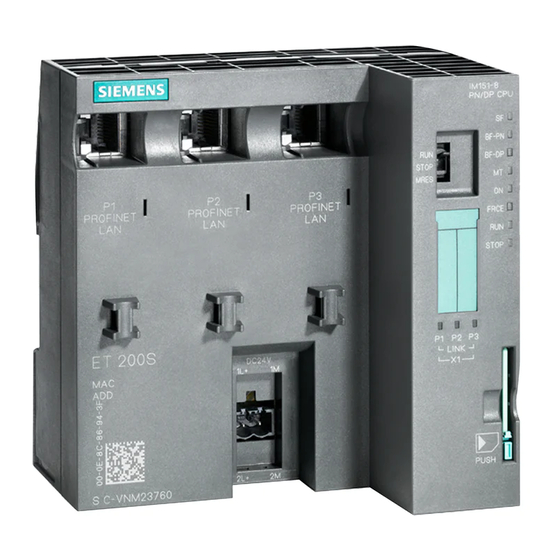
SIMATIC IM 151/CPU
Siemens SIMATIC IM 151/CPU Manuals
Manuals and User Guides for Siemens SIMATIC IM 151/CPU. We have
1
Siemens SIMATIC IM 151/CPU manual available for free PDF download: Manual
Siemens SIMATIC IM 151/CPU Manual (218 pages)
Interface Module for ET 200S Distributed I/O System
Brand:
Siemens
| Category:
Control Unit
| Size: 1.8 MB
Table of Contents
Table of Contents
7
1 Product Overview
15
What Is the IM 151/CPU Interface Module
16
View of the ET 200S Distributed I/O System with the IM 151/CPU
17
IM 151/Cpu
17
Guide to the ET 200S Manuals
19
Components and the Manuals Required for Them
19
With the IM 151/CPU
20
Topics of the Manuals in the ET 200S Manual Package
20
2 Addressing
21
Slot-Oriented Addressing
22
Structure of the Default Address Area
22
Slots on the ET 200S
22
Example of Address Assignment for I/O Modules
23
Addresses of the ET 200S I/O Modules
23
User-Defined Addressing
24
Structure of the Address Area for User-Defined Addressing
24
Data Transfer with the DP Master
25
Principles of Data Transfer between the DP Master and the ET 200S
25
Examples of the Maximum Configuration
26
Accessing the Intermediate Memory in the IM 151/CPU
27
Accessing the Address Areas
27
Addressing Interface in STEP 7 V5.1 (Extract)
28
Example of a PROFIBUS Network
32
The PG/OP Accesses the ET 200S Via the DP Interface in the
34
The Programming Device Accesses the ET 200S on a
34
3 ET 200S in the PROFIBUS Network
35
Setting the PROFIBUS Address
35
Setting the PROFIBUS Address
36
Network Components
37
Connecting the DP Network
38
Functions Via the Programming Device/Op
39
Direct Communication
40
Direct Communication with the IM 151/CPU
40
4 Commissioning and Diagnostics
43
Configuring the IM 151/CPU
44
Configuration Options
44
Resetting the Memory of the IM 151/CPU
46
Ways to Reset the Memory
46
How to Use the Mode Selector to Reset the Memory
47
Internal CPU Events at Memory Resetting
47
Commissioning and Startup of the ET 200S
49
Diagnostics Using Leds
51
Leds for PROFIBUS-DP
52
Diagnostics Via Diagnostic Address with STEP 7
53
Diagnostic Addresses for the DP Master and ET 200S
53
Responses to Operating Mode Changes and Interruptions in User Data Transfer in the DP Master/Et and the ET 200S with the IM 151/CPU
54
Slave Diagnosis
56
Format of the Slave Diagnostic Data
57
Station Status 1 to 3
58
Structure of Station Status 1 (Byte 0)
58
Structure of Station Status 2 (Byte 1)
59
Structure of Station Status 3 (Byte 2)
59
Master PROFIBUS Address
60
Structure of the Master PROFIBUS Address (Byte 3)
60
Manufacturer ID
61
Structure of the Manufacturer Identification (Bytes 4 and 5)
61
Structure of the Module Diagnosis
62
Module Status
63
Structure of the Module Status
63
Structure of the Station Diagnosis
64
Structure of the Station Diagnosis
65
Additional Interrupt Information and Diagnostic Data
65
System Status List (SSL)
66
SSL Sublists of the IM 151/CPU
66
Attributes of the Device Database (DDB) File
70
Mode Selector
72
Positions of the Mode Selector
72
Leds for CPU Functionality
73
Principle Behind Forcing
74
Available Mmcs
76
Position of the Memory Card Slot for the MMC on the IM 151/CPU
77
Firmware Update with MMC
78
Backing up the Operating System
79
Features of the Clock
80
Overview of the Blocks
81
Obs for Cycle and Restart
82
Obs for Interrupts
82
Obs for Error/Fault Responses
83
Parameterization of the Reference Junction
86
Example of a Parameterization Dialog Box for the CPU Module Data in STEP 7 V5.1
87
Result of the Preset/Actual Comparison in Modules that Cannot be Parameterized
89
Result of the Preset/Actual Comparison in the Case of Parameterizable
89
Modules with the Power Module Switched on
89
Result of the Preset/Actual Comparison in the Case of Parameterizable Modules with the Power Module Switched off
89
Terminal Assignment of the IM 151/CPU Interface Module
93
Basic Circuit Diagram for the IM 151/CPU
94
Basic Circuit Diagram for the IM 151/CPU FO
94
Component Parts of the Cycle Time
100
Process Image Updating
101
Dependency of the User Program Scanning Time
102
Updating the S7 Timers
102
Extending the Cycle by Nesting Interrupts
103
Shortest Response Time
105
Longest Response Time
106
Interrupt Response Times of the IM 151/CPU (Without Communication)
107
Description of Byte 0 of the Address Area Identifiers
129
Description of Byte 1 of the Address Area Identifiers
129
Standard Section of the Parameter Assignment Frame
132
General Section of the Parameter Assignment Frame for the IM 151/CPU
133
Example: FB with Unpacked Addresses
193
Example: FB with Packed Addresses
194
Example: Rewiring of the Signals
195
Advertisement
Advertisement
Related Products
Siemens IM 155-6 PN ST
Siemens SIMATIC IM 153-2
Siemens IM 151-7
Siemens SIMATIC IM151-1 STANDARD
Siemens SIMATIC IM 155-5 PN ST
Siemens SIMATIC IM 178-4
Siemens IM 328-N
Siemens IM 329-N
Siemens IP-Module CFVA-IP
Siemens 4AI I 4WIRE HART
Siemens Categories
Industrial Equipment
Controller
Control Unit
Oven
Washer
More Siemens Manuals
Login
Sign In
OR
Sign in with Facebook
Sign in with Google
Upload manual
Upload from disk
Upload from URL