Sign In
Upload
Manuals
Brands
Siemens Manuals
Control Unit
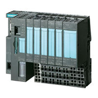
IM 151-7
Siemens IM 151-7 Manuals
Manuals and User Guides for Siemens IM 151-7. We have
1
Siemens IM 151-7 manual available for free PDF download: Manual
Siemens IM 151-7 Manual (212 pages)
CPU Interface Module
Brand:
Siemens
| Category:
Control Unit
| Size: 1.53 MB
Table of Contents
A5E00058783
2
1 Preface
3
Table of Contents
11
2 Product Overview
19
What Is the IM 151-7 CPU Interface Module
20
Limitations in the Use of ET 200S Modules
20
View of the ET 200S Distributed I/O System with the IM 151-7 CPU
21
Guide to the ET 200S Manuals
23
Components and the Manuals Required for Them
23
Components and the Manuals Required for Them (Continued)
24
Topics of the Manuals in the ET 200S Manual Package
25
Glossary
26
3 Getting Started
27
1St Step: Installing the IM 151-7 CPU (ET 200S) and S7-300
29
Installing the IM 151-7 CPU (ET 200S)
29
2Nd Step: Wiring the IM 151-7 CPU (ET 200S) and S7-300
30
Illustration Showing the S7-300
31
3Rd Step: Commissioning the IM 151-7 CPU (ET 200S)
32
4Ht Step: Configuring the IM 151-7 CPU for Stand-Alone Operation (MPI)
33
5Th Step: Programming the IM 151-7 CPU
35
6Th Step: Test Run
36
7Th Step: Upgrading the IM 151-7 CPU as an I Slave and Commissioning the S7-300
37
8Th Step: Configuring the IM 151-7 CPU as an I Slave and the S7-300
38
9Th Step: Programming the IM 151-7 CPU and the S7-300 CPU
42
10Th Step: Commissioning and Test Run of the IM 151-7 CPU and S7-300
45
4 Addressing
49
Slot-Oriented Addressing of the I/O Modules
50
Structure of the Default Address Area
50
Slots on the ET 200S
50
Addresses of the ET 200S I/O Modules
51
User-Oriented Addressing of the I/O Modules
52
Example of Address Assignment for I/O Modules
52
Structure of the Address Area for User-Oriented Addressing
52
Data Interchanger with the DP Master
53
Principles of Data Transfer between the DP Master and the ET 200S
53
Accessing the Intermediate Memory in the IM 151-7 CPU
55
Accessing the Address Areas
55
Addressing Interface in STEP 7 V5.1 (Extract)
56
5 ET 200S in the PROFIBUS Network
59
Example of a PROFIBUS Network
60
ET 200S in the PROFIBUS Network
60
Setting the Mode of the DP Interface at the IM 151-7 CPU
61
Behavior of the IM 151-7 CPU Depending on the DP Interface Setting
62
The PD/OP Accesses the ET 200S Via the DP Interface in the DP Master
63
The PD Directly Accesses the ET 200S
63
Network Components
64
Connecting the DP Network
65
PROFIBUS Address
66
Functions Via the PD/OP
67
Principle Behind Forcing
68
Direct Communication
70
Direct Communication with the IM 151-7 CPU
70
6 ET 200S in the MPI Network
73
ET 200S in the MPI Network
73
Example of an MPI Network
74
MPI Address
75
Example of the Structure with the IM 151-7 CPU Acting as the DP Master
77
DP Master Module
77
Mounting the DP Master Module
78
7 DP Master Module
79
Commissioning the IM 151-7 CPU as a DP Master
79
Event Recognition of the IM 151-7 CPU as a DP Master
81
8 Commissioning and Diagnostics
83
Configuration Options
84
Configuring the IM 151-7 CPU
84
Ways to Reset the Memory
86
Resetting the Memory of the IM 151-7 CPU
86
How to Use the Mode Selector to Reset the Memory
87
Internal CPU Events at Memory Resetting
87
Commissioning and Startup of the IM 151-7 CPU as an I Slave
89
Diagnostics Using Leds
91
LED Display for PROFIBUS-DP (IM 151-7 CPU Is an I Slave)
92
LED Display for PROFIBUS-DP (IM 151-7 CPU Is a Master)
93
Diagnostic Addresses for the DP Master and ET 200S
94
Diagnostics Via Diagnostic Address with STEP 7
94
Responses to Operating Mode Changes and Interruptions in User Data Transfer in the DP Master and the ET 200S with the IM 151-7 CPU as an I Slave
95
Evaluation of RUN-STOP Transitions in the DP Master/ ET 200S with
96
Format of the Slave Diagnostic Data
97
Slave Diagnostics with IM 151-7 CPU Used as an Intelligent Slave
97
Structure of Station Status 1 (Byte 0)
98
Structure of Station Status 2 (Byte 1)
99
Structure of Station Status 3 (Byte 2)
99
Structure of the Master PROFIBUS Address (Byte 3)
100
Structure of the Manufacturer Identification (Bytes 4 and 5)
100
Structure of the Module Diagnosis for the IM 151-7 CPU
101
Module Diagnostics
101
Module Status
102
Structure of the Module Status
103
Structure of the Interrupt Status
104
Byte Y+4 to Y+7 for the Diagnostic Interrupt
105
Byte Y+4 to Y+7 for Diagnostic Interrupt (SFB 75)
106
Diagnostic Data of the Electronic Modules
107
Structure of the Diagnostic Data Using a 4 Channel Mixed Module as an Example
108
Bytes 0 and 1 of the Diagnostic Data
109
Identifiers of the Module Classes
109
Bytes 4 to 7 of the Diagnostic Data
110
Single Fault of a Channel
111
Channel-Specific Diagnostic Data from Byte 8 Onwards
111
Example: ET 200S Module: 2 AI U (6ES7 134-4FB00-0AB0) each with Diagnostics for Channel 0 and 1
112
9 Functions of the IM 151-7 CPU
113
Attributes from the Device Database (DDB) File
114
Data for the PROFIBUS-DP
114
Positions of the Mode Selector
116
The Mode Selector and Leds
116
Leds for CPU Functionality
117
SIMATIC Micro Memory Card
118
Available Mmcs
119
Position of the Memory Card Slot for the MMC on the IM 151-7 CPU
121
Firmware Update with MMC
122
Backing up the Operating System
123
Memory Areas of the IM 151-7 CPU
124
Memory Concept
124
Retentive Behavior of the Memory Objects
126
Retentive Behavior of the Dbs in IM 151-7 CPU
126
Load and Working Memory
127
Memory Functions
127
Address Areas of the System Memory
132
Processing Steps Within a Cycle
133
Handling Recipe Data
135
Handling Data in Dbs
135
Handling Measured Value Archives
136
Storing/Download Entire Projects On/From Micro Memory Cards
137
Interfaces
138
Features of the Clock
140
S7 Connections
141
Distribution of the S7 Connections
144
Availability of the S7 Connections
145
Communication Utilities of the IM 151-7 CPU
146
GD Resources of the IM 151-7 CPU
149
Routing
150
Routing Gateway
151
Routing - Teleservice Application Example
152
Data Consistency
153
Overview of the Blocks
154
IM 151-7 Cpu
154
Parameters
156
Of Thermocouples
158
Parameterization of the Reference Junction
158
Example of a Parameterization Dialog Box for the CPU Module Parameters in STEP 7 V5.2 + SP1
159
Removal and Insertion of Modules During Operation
160
Result of the Preset/Actual Comparison in Modules that Cannot be
161
Parameterized
161
Result of the Preset/Actual Comparison in the Case of Parameterizable
161
Result of the Preset/Actual Comparison in the Case of Parameterizable Modules with the Power Module Switched off
162
Switching Power Modules off and on During Operation
163
10 Cycle and Response Times
165
Component Parts of the Cycle Time
166
Operating System Processing Time in the Scan Cycle Checkpoint
167
Dependency of the User Program Scanning Time
168
Extending the Cycle by Nesting Interrupts
168
With the IM 151-7 CPU
169
11 Technical Specifications
169
Shortest Response Time
170
Longest Response Time
171
Interrupt Response Times of the IM 151-7 CPU (Without Communication)
172
Technical Specifications
173
Technical Specifications of the IM 151-7 CPU
174
Terminal Assignment for the Interface Module IM 151-7 CPU
175
Basic Circuit Diagram for the IM 151-7 CPU
176
12 Changing IM 151-7 CPU (6ES7 151-7Ax00
187
13 Position of the IM 151-7 CPU in the CPU Range
187
Differences to Selected S7-300 Cpus
188
Example: FB with Unpacked Addresses
189
Porting the User Program
189
Example : Replacements under Tools ! Rewire
190
Advertisement
Advertisement
Related Products
Siemens IM 155-6 PN ST
Siemens SIMATIC IM 153-2
Siemens SIMATIC IM 178-4
Siemens SIMATIC IM 151/CPU
Siemens SIMATIC IM151-1 STANDARD
Siemens SIMATIC IM 155-5 PN ST
Siemens IM 328-N
Siemens IM 329-N
Siemens IP-Module
Siemens IP-Module CVVA-IP
Siemens Categories
Industrial Equipment
Controller
Control Unit
Oven
Washer
More Siemens Manuals
Login
Sign In
OR
Sign in with Facebook
Sign in with Google
Upload manual
Upload from disk
Upload from URL