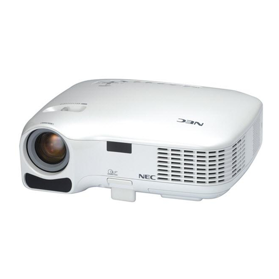
NEC LT30 - XGA DLP Projector Installation And Assembly Manual
Lt30/35 cm guide
Hide thumbs
Also See for LT30 - XGA DLP Projector:
- Specifications (2 pages) ,
- Control commands (54 pages)
Table of Contents
Advertisement
Quick Links
This product is UL Listed. It
must be installed by a qualified
R
professional installer.
Read instruction sheet before you start installation and assembly.
• Installer must verify that the ceiling will safely support four times the combined weight of all attached equipment and
hardware.
IMPORTANT! Be sure not to touch the projector while tightening the set screw on the
ball and socket mount. This may cause the image to be unaligned when you let go.
IMPORTANT! Turn to the appropriate page for your ceiling installation.
For installation to Wood Joist Finished Ceiling, Exposed Wood Joists, or Wood Beam
Ceiling, see page 3.
For installation to Concrete Ceilings, see page 4.
For installation to Threaded Rod, see page 5.
For installation to Extension Column, see page 5.
ADAPTER PLATE
Visit the Peerless Web Site at www.peerlessmounts.com
Installation and Assembly -
GENERIC
Mount and adapter plate for
NEC™ LT30CM Projector
WARNING
1 of 7
For customer service call 1-800-729-0307 or 708-865-8870.
Maximum Load Capacity: 50 lb
PRS SERIES
PROJECTOR
MOUNT
ISSUED: 10-13-05 SHEET #: 055-9445-2 03-31-06
Model: LT30CM
Advertisement
Table of Contents

Summary of Contents for NEC LT30 - XGA DLP Projector
- Page 1 Mount and adapter plate for Installation and Assembly - Model: LT30CM NEC™ LT30CM Projector Maximum Load Capacity: 50 lb This product is UL Listed. It must be installed by a qualified professional installer. Read instruction sheet before you start installation and assembly.
-
Page 2: Parts List
Before you start check the parts list to insure all of the parts shown are included. Parts List Description Qty. Part AA adapter plate 055-2641 BB M4 x 12mm socket pin serrated washer head pin screw 510-2079 CC M4 .7 x 20mm knurled knob 560-7137 DD retaining spacer .235 x .375 x .38H 590-2150... -
Page 3: Installation To Wood Joist Finished Ceilings, Exposed Wood Joists, Or Wood Beam Ceilings
Installation To Wood Joist Finished Ceilings, Exposed Wood Joists, or Wood Beam Ceilings Drill two 5/32" (4 mm) dia. holes to a minimum depth of 2.5" (64 mm). Attach projector mount assembly (A) with two #14 x 2.5" (6 mm x 65 mm) wood screws (F) and two flat washers (E) as shown in figure 1 or figure 2 depending on joist orientation. -
Page 4: Installation To Concrete Ceilings
Installation to Concrete Ceilings Drill two 1/4" (6 mm) dia. holes to a minimum depth of 2.5" (64 mm). Attach projector mount assembly (A) using two concrete anchors (G), two flat washers (E), and two #14 x 2.5" wood screws (F) as shown in Illustration A and 1, 2, and 3 (below). -
Page 5: Installation To Threaded Rod
Installation to Threaded Rod Attach projector mount assembly (A) to two 3/8-16 threaded rods (not included) using two 3/8-16 hex thin nylon- insert locknuts (not included) as shown in figure 1.1 or figure 1.2. Skip to step 6. 3/8 -16 THREADED ROD 3/8 -16 THREADED ROD (NOT INCLUDED) (NOT INCLUDED) -
Page 6: Final Assembly
Installation of Adapter Plate *Notch indicates front of projector. Flip projector upside down. Using holes indicated Close adapter plate (AA) and fasten with thumb below, attach adapter plate (AA) to projector using screw (CC). two M4 x 12 mm screws (BB) using 4 mm security t-wrench (B). -
Page 7: Projector Alignment
Slide connection block with projector into projector mount IMPORTANT: For security installations, insert assembly (A) as shown. Tighten captive screw to secure one #10-32 x 1/4" socket pin screw (D) through projector to projector mount assembly (A). projector mount assembly (A) and into connection block as shown.


