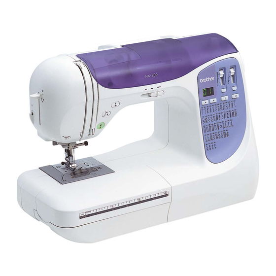
Brother NX200 Service Manual
Hide thumbs
Also See for NX200:
- Operation manual (111 pages) ,
- Manual de instrucciones (108 pages) ,
- Manuel d'instructions (108 pages)
Advertisement
Table of Contents
Advertisement
Table of Contents

Summary of Contents for Brother NX200
-
Page 2: Table Of Contents
This was produced based on up-to-date product specifications at the time of issue, but there may have been changes of specifications for the purpose of improvements. Contact manufacturer or local sales company for information concerning such changes. Brother Industries, Ltd. Nagoya, Japan CAUTION 1. -
Page 3: Disassembly
Disassembly 2 - 1... -
Page 4: Front Cover Disassembly (Operation Pcb Assy Disassembly)
Main unit Main parts Front cover disassembly (operation PCB assy disassembly) 1. Remove the screws 1 (four) and remove the operation PCB assembly 1, rubber keys 2, key top rear plate 3 and VR key tops 4 (two). 2 - 2... -
Page 5: Presser Foot Lifter Removal
Modules Needle-presser module 2-37 Presser foot lifter removal 1. Remove retaining ring E4. 2. Remove the presser lift shaft 1, presser foot lifter 2. and washers (two). 3. Remove retaining ring E4 from the presser lift shaft 1. 2 - 3... - Page 6 2 - 4...
-
Page 7: Assembly
Assembly 3 - 1... -
Page 8: Main Parts
Main unit Main parts 3-35 Front cover assembly (assembling the operation PCB holder) 1. Attach the rubber keys 1 to the operation PCB holder 2. 2. Attach the VR key tops 3 (two) and key top rear plate 4 to the operation PCB holder 2. -
Page 9: Needle-Presser Module
Modules Needle-presser module 3-46 Presser foot lifter attachment Retaining ring E4 1. Attach retaining ring E4 to the presser lift shaft 1. 2. Apply a small amount of Molykote EM30L to the presser lift shaft 1. 3. Insert the presser lift shaft 1 into the hole 2 in the thread releaser assy. and attach the washers (two). - Page 10 3 - 4...
- Page 11 Adjustment 4 - 1...
-
Page 12: Test Mode
Test Mode Starting test mode • With the front cover in place Press while turning the power on; the buzzer will sound four times, and test mode will start. • Without the front cover in place Press SW1 and SW3 on the main PCB assy. while turning the power on; the buzzer will sound four times, and test mode will start. - Page 14 NX200 NX200 13C03HF882S60...


