Sign In
Upload
Manuals
Brands
Siemens Manuals
Accessories
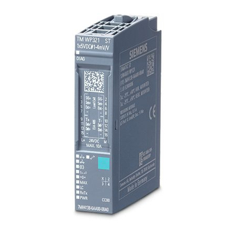
SIWAREX WP321
Siemens SIWAREX WP321 Manuals
Manuals and User Guides for Siemens SIWAREX WP321. We have
2
Siemens SIWAREX WP321 manuals available for free PDF download: Operating Instructions Manual, Manual
Siemens SIWAREX WP321 Manual (126 pages)
Electronic weighing system
Brand:
Siemens
| Category:
Accessories
| Size: 2.87 MB
Table of Contents
Table of Contents
3
1 Introduction
9
Purpose of the Manual
9
Basic Knowledge Required
9
Manual - Range of Validity
9
2 Safety Notes
11
General Safety Instructions
11
IT Security
12
3 Description
13
Product Overview
13
Area of Application
13
System Integration in SIMATIC
13
Figure 3-1 System Overview
14
Customer Benefits
15
Scope of Delivery
16
4 Application Planning
17
Functions
17
Parameter Assignment Options
18
Parameter Assignment with the PC
18
Parameter Assignment with the SIMATIC Panel
18
Figure 4-1 SIWATOOL Overview
18
5 Mounting
19
Installation Guideline
19
EMC-Compliant Setup
20
Introduction
20
Possible Effects of Interference
20
Coupling Mechanisms
20
Five Basic Rules for Securing EMC
21
Mounting on the SIMATIC ET 200SP
23
Figure 5-1 Installation of the I/O or SIWAREX Modules
23
Configuration of the Hardware in SIMATIC
24
6 Connection
25
Figure 6-1 SIWAREX WP321 Process Terminals on the Base Unit
25
24 V Connection
26
Connecting the Load Cells
26
Table 6- 1 Connection of the 24 V Supply
26
Figure 6-2 Shielding in the Screw Gland
27
Shield Connection
28
Figure 6-3 Shield Connection and Shield Terminal
28
Connection of RS485 Serial Interface
29
Table 6- 2 Termination of RS485 Serial Interface
29
Connection of Siebert Display Via RS485
30
Table 6- 3 Settings of Siebert Display S102
30
Figure 6-4 Connection of Siebert Display S102
30
7 Commissioning
31
Factory-Set Parameters
31
Commissioning Tools
31
5-Minute Quick Start with the Operator Panel and the Ready-For-Use Software
32
Start
32
Figure 7-1 Quick Start Step 1
32
Factory Setting of the Parameters
33
Figure 7-2 Quick Start Step 2
33
Selecting the Calibration Method
34
Figure 7-3 Quick Start Step 3
34
Defining the Calibration Weights
35
Figure 7-4 Quick Start Step 4A
35
Setting Calibration Points
36
Figure 7-5 Quick Start Step 5A
36
Calibrating the Scale Automatically
37
Figure 7-6 Quick Start Step 4B
37
Performing the Automatic Calibration
38
Checking the Scale Following Calibration
38
Figure 7-7 Quick Start Step 5B
38
5-Minute Quick Start with SIWATOOL
39
Activate Service Mode
39
Load Factory Setting
39
Figure 7-8 Quick Setup with Marked Parameters
39
Input of Required Parameters
40
Complete Automatic Calibration
40
Figure 7-9 Sending/Receiving a Data Record with SIWATOOL V7
40
Receive All Data
41
Checking the Scale Following Calibration
41
Service with the SIWATOOL Program
42
Windows and Functions of SIWATOOL
42
Figure 7-10 Layout of the SIWATOOL User Interface
42
Offline Parameter Assignment
43
Online Parameter Assignment
43
Available Help Options
44
Entering Parameters with SIWATOOL
44
8 Scale Parameters and Functions
45
Parameters and Functions
45
DR 2 Command Code
45
DR 3 Calibration Parameters
46
Table 8- 1 Assignment of Data Record 3
46
Scale Name
48
Unit of Weight
48
Gross Identifier
48
Maximum Weighing Range
49
Calibration Weights 0, 1, 2 and Calibration Digits 0, 1, 2
49
Scale Interval
49
Automatic Zero Adjustment
49
Decimal Places for Process Values
49
Maximum Tare Load
49
Maximum Negative Zeroing Limit
50
Maximum Positive Zeroing Limit
50
Standstill Range
51
Standstill Time
51
Figure 8-1 Standstill Monitoring
51
Standstill Waiting Time
52
Low-Pass Filter Limit Frequency
52
Low-Pass Filter Number
52
Figure 8-2 Step Response of the Digital Low-Pass Filter When Fg = 2 Hz
52
Mean Value Filter Depth
53
Calibration Procedure
54
Calibration with Calibration Weights
54
Figure 8-3 Calibration Digits and Calibration Weight
55
Figure 8-4 Linearizing the Scale's Characteristic Curve
56
Automatic Calibration
57
DR 4 Output of Calculated Calibration Digits
58
Calibration Digits 0, 1, 2 (Calculated)
58
Table 8- 2 Assignment of Data Record 4
58
DR 5 Zeroing Memory
59
Table 8- 3 Assignment of Data Record 5
59
Effective Tare Weight - from Specification
60
Effective Tare Weight (Semi-Automatic)
60
Zero Weight (Semi-Automatic)
60
Current Zero Tracking Weight
60
Dead Load
60
DR 6 Limit Value Settings
61
Table 8- 4 Assignment of Data Record 6
61
Limit Value 1 ON, Limit Value 2 ON, Limit Value 1 OFF, Limit Value 2 off
63
Limit Value "Empty" on
63
Figure 8-5 Limit Value Configuration
63
Delay Time for Limits
64
DR 9 Module Information
65
Table 8- 5 Assignment of Data Record 9
65
DR 10 Load Cell Parameters
67
Table 8- 6 Assignment of Data Record 10
67
50/60 Hz Toggling
68
Number of Support Points
68
Load Cell Characteristic Value
68
Rated Load of a Load Cell
68
DR 13 RS485 Parameters
69
Table 8- 7 Assignment of Data Record 13
69
RS485 Protocol
70
RS485 Baud Rate
70
RS485 Character Parity
70
Decimal Place for Siebert Indicator
70
DR 14 SIMATIC Interface Parameters
71
Table 8- 8 Assignment of Data Record 14
71
Selection of Process Value 1, 2
72
Table 8- 9 Selection Table for Process Value 1,2
72
DR 15 Manual Tare Specification
73
Specification of Tare Weight
73
Table 8- 10 Assignment of Data Record 15
73
DR 30 Current Process Values
74
Table 8- 11 Assignment of Data Record 30
74
Gross Process Weight
76
Net Process Weight
76
Tare Process Weight
76
Gross / Net Weight
76
Gross / Net Weight with Increased Resolution (X 10)
76
Tare Weight
76
Refresh Counter for Process Values
76
DR 31 Advanced Current Process Values
77
Unfiltered Digit Value
77
Filtered Digit Value
77
Table 8- 12 Assignment of Data Record 31
77
Refresh Counter for Process Values
78
DR 32 Message Display
79
Table 8- 13 Assignment of Data Record 32
79
Error Bytes 0 to 7
81
DR 34 ASCII Main Display Value
82
Table 8- 14 Assignment of Data Record 34
82
Content of Main Display as ACII String
83
9 Messages
85
Message Types
85
Message Paths
86
Evaluating Messages with the Help of SIWATOOL
86
Detecting Messages with the Help of FB SIWA
86
Message List
87
System Status Message List
87
Technology Error Message List
87
Data and Operating Errors Message List
88
Messages by Leds on the Module
89
10 Command Lists
91
Table 10- 1 Command Groups of the SIWAREX WP321
93
11 Communication in SIMATIC S7-300/1200/1500
95
General Information
95
Structure of the Program "Ready for Use
95
Table 11- 1 Memory Requirements of the Function Block
95
Advantages of Task Sharing
96
Hardware Configuration of the Electronic Weighing System
97
Figure 11-1 Hardware Configuration in the TIA Portal
97
Figure 11-2 Start Address of Module in TIA Portal
98
Figure 11-3 Configuration of Interrupts in TIA Portal
98
Figure 11-4 HW ID of Module in TIA Portal
98
Calling of Function Block
99
Figure 11-5 Calling of WP321DR Block in User Program
99
Working with the Function Block
100
Figure 11-6 CMD Command Mailboxes
100
I/O Interface of Function Block
103
Error Codes of Function Block
103
Table 11- 2 I/O Data of the Function Block
103
Table 11- 3 Statuses/Errors When Working with the Function Block
103
Diagnostics Messages
104
Table 11- 4 Diagnostics Messages
104
Diagnostics Interrupts
105
Hardware Interrupts
105
Figure 11-7 Configuration of Hardware Interrupts for S7-1500
106
12 Technical Data
107
Technical Specifications
107
Electrical, EMC and Climatic Requirements
110
Table 12- 1 Interference Emission (Industrial Area): en 61000-6-4
111
Table 12- 2 Interference Immunity (Industrial Environment): en 61000-6-2
112
Table 12- 3 Operating Conditions to IEC 60721
113
Table 12- 4 Climatic Requirements
113
Approvals
114
13 Accessories
115
Table 13- 1 Essential Accessories
115
Table 13- 2 Optional Accessories
115
Appendix
119
Technical Support
119
A.1 Technical Support
119
ESD Guidelines
121
B.1 ESD Guidelines
121
Figure B-1 Electrostatic Voltages Which an Operator Can be Subjected to
122
List of Abbreviations
123
C.1 List of Abbreviations
123
Index
125
Advertisement
Siemens SIWAREX WP321 Operating Instructions Manual (132 pages)
Electronic weighing system
Brand:
Siemens
| Category:
Accessories
| Size: 2.96 MB
Table of Contents
Table of Contents
3
1 Introduction
9
Purpose of this Documentation
9
Document History
9
Mounting
9
Product Compatibility
10
Checking the Consignment
10
Security Information
10
Transportation and Storage
11
Notes on Warranty
11
Technical Data
11
Basic Knowledge Required
12
2 Safety Notes
13
General Safety Instructions
13
3 Description
15
Product Overview
15
Area of Application
15
System Integration in SIMATIC
15
Customer Benefits
16
4 Application Planning
19
Functions
19
Parameter Assignment Options
19
Parameter Assignment with the PC
19
Parameter Assignment with the SIMATIC Panel
20
5 Mounting
21
Safety Notices for Installation
21
Safety Information According to FM and UL
21
Installation Guideline
22
EMC-Compliant Setup
22
Introduction
22
Possible Effects of Interference
23
Coupling Mechanisms
23
Five Basic Rules for Securing EMC
23
Mounting on the SIMATIC ET 200SP
24
Configuration of the Hardware in SIMATIC
25
6 Connecting
27
24 V Connection
27
Connection of Analog Load Cells
27
Connecting SIWAREX JB to the Electronic Weighing System and Load Cell
28
Wiring Diagrams
28
Load Cells with Four-Wire System
28
Load Cells with Six-Wire System
30
Connecting the Cable
31
Shield Connection
31
Connection of RS485 Serial Interface
32
Connection of Siebert Display Via RS485
33
Connection of the SIWAREX DB
34
Connect SIWAREX DB to SIWAREX WP Electronic Weighing System and Load Cell
34
Connect the Cable
35
7 Commissioning
37
Factory-Set Parameters
37
Commissioning Tools
37
5-Minute Quick Start with the Operator Panel and the Ready-For-Use Software
38
Start
38
Factory Setting of the Parameters
39
Selecting the Calibration Method
40
Defining the Calibration Weights
41
Setting Calibration Points
42
Calibrating the Scale Automatically
43
Performing the Automatic Calibration
44
Checking the Scale Following Calibration
44
Fast Commissioning (Quick Start) with SIWATOOL
45
Service with the SIWATOOL Program
45
Establish Communication to SIWAREX WP321
45
Calibration
46
Selecting the Calibration Method
46
Calibration with Calibration Weight
47
Automatic Calibration (Without Calibration Weight)
50
Receive All Data
55
Service with the SIWATOOL Program
56
Windows and Functions of SIWATOOL
56
Offline Parameter Assignment
57
Online Parameter Assignment
57
Available Help Options
58
Entering Parameters with SIWATOOL
58
8 Scale Parameters and Functions
59
Parameters and Functions
59
Assigning Parameters to the Electronic Weighing System with SIWAREX DB
59
DR 2 Command Code
60
DR 3 Calibration Parameters
60
Scale Name
62
Unit of Weight
63
Gross Identifier
63
Maximum Weighing Range
63
Calibration Weights 0, 1, 2 and Calibration Digits 0, 1, 2
63
Scale Interval
63
Automatic Zero Adjustment
63
Decimal Places for Process Values
64
Maximum Tare Load
64
Maximum Negative Zeroing Limit
64
Maximum Positive Zeroing Limit
64
Standstill Range
64
Standstill Time
65
Standstill Waiting Time
65
Low-Pass Filter Limit Frequency
66
Low-Pass Filter Number
66
Mean Value Filter Depth
67
Calibration Procedure
67
Calibration with Calibration Weights
67
Automatic Calibration
70
DR 4 Output of Calculated Calibration Digits
70
Calibration Digits 0, 1, 2 (Calculated)
71
DR 5 Zeroing Memory
71
Effective Tare Weight - from Specification
72
Effective Tare Weight (Semi-Automatic)
72
Zero Weight (Semi-Automatic)
72
Current Zero Tracking Weight
73
Dead Load
73
DR 6 Limit Value Settings
73
Limit Reference
74
Limit Value 1 ON, Limit Value 2 ON, Limit Value 1 OFF, Limit Value 2 off
75
Limit Value "Empty" on
75
Delay Time for Limits
76
DR 9 Module Information
76
DR 10 Load Cell Parameters
77
Selection of the Sampling Rate
78
Number of Support Points
79
Load Cell Characteristic Value
80
Rated Load of a Load Cell
80
DR 13 RS485 Parameters
80
RS485 Protocol
81
RS485 Baud Rate
81
RS485 Character Parity
81
Decimal Place for Siebert Indicator
81
DR 14 SIMATIC Interface Parameters
81
Selection of Process Value 1, 2
82
DR 15 Manual Tare Specification
83
Specification of Tare Weight
84
DR 30 Current Process Values
84
Gross Process Weight
86
Net Process Weight
86
Tare Process Weight
86
Gross / Net Weight
86
Gross / Net Weight with Increased Resolution (X 10)
86
Tare Weight
86
Refresh Counter for Process Values
87
DR 31 Advanced Current Process Values
87
Unfiltered Digit Value
87
Filtered Digit Value
88
Refresh Counter for Process Values
88
DR 32 Message Display
88
Error Bytes 0 to 7
90
DR 34 ASCII Main Display Value
90
Content of Main Display as ACII String
91
DR 70 SIWAREX DB Parameter
91
DR 80 SIWAREX DB Process Status
92
DR 81 SIWAREX DB Process Status Advanced
95
DR 82 SIWAREX DB Device Information
96
9 Messages
97
Message Types
97
Message Paths
97
Evaluating Messages with the Help of SIWATOOL
98
Evaluating Messages with the Help of SIMATIC FB
98
Message List
98
System Status Message List
98
Technology Error Message List
99
Data and Operating Errors Message List
99
Messages by Leds on the Module
100
10 Command Lists
101
11 Communication in SIMATIC S7-300/400/1200/1500
103
General Information
103
Structure of the Program "Ready for Use
103
Advantages of Task Sharing
103
Hardware Configuration of the Electronic Weighing System
104
Calling of Function Block
106
Working with the Function Block
107
I/O Interface of Function Block
110
Error Codes of Function Block
110
Diagnostics Messages
111
Diagnostics Interrupts
111
Hardware Interrupts
112
12 Technical Data
115
Electrical, EMC and Climatic Requirements
117
Reliability
120
Approvals
120
13 Ordering Data
123
Certificates and Support
125
Technical Support
125
A.1 Technical Support
125
ESD Guidelines
127
B.1 ESD Guidelines
127
Abbreviations
129
List of Abbreviations
129
C.1 List of Abbreviations
129
Index
131
Advertisement
Related Products
Siemens SIWAREX WP241
Siemens SIWAREX WP251
Siemens WiPS-200 Series
Siemens SITRANS WFS320
Siemens SITRANS WS300
Siemens Sitrans WM100
Siemens SITRANS WW100
Siemens RUGGEDCOM WIN7018
Siemens SIWAREX WL250 ST-S SA
Siemens SIWAREX WL290 DB-S CA
Siemens Categories
Industrial Equipment
Controller
Control Unit
Oven
Washer
More Siemens Manuals
Login
Sign In
OR
Sign in with Facebook
Sign in with Google
Upload manual
Upload from disk
Upload from URL