Sign In
Upload
Manuals
Brands
Siemens Manuals
Controller
7SR224
User Manuals: Siemens 7SR224 Overcurrent Relay
Manuals and User Guides for Siemens 7SR224 Overcurrent Relay. We have
7
Siemens 7SR224 Overcurrent Relay manuals available for free PDF download: Technical Manual, Manual, Description & Operation, Technical Reference
Siemens 7SR224 Technical Manual (350 pages)
Recloser Controller
Brand:
Siemens
| Category:
Controller
| Size: 14.76 MB
Table of Contents
Table of Contents
4
Description of Operation
3
Section 1: Introduction
8
Current Transformer Circuits
8
External Resistors
8
Fibre Optic Communication
8
Front Cover
8
Front Fascia
8
Table 1-1 7SR224 Ordering Options
9
Figure 1.5-1 Functional Diagram of 7SR224 Relay Showing Possible External Connections
10
Section 2: Hardware Description
11
General
11
Case
11
Table 2-1 Summary of Controller Relay Configurations
11
Front Cover
12
Power Supply Unit (PSU)
12
Operator Interface/ Fascia
12
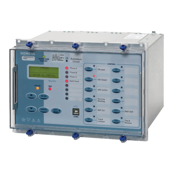
Figure 2.5-1 7SR224 with 12 Function Keys and 3 + 8 Leds in E10 Case
12
Current Inputs
14
Voltage Inputs
14
Binary Inputs
14
Figure 2.8-1 Binary Input Logic
15
Binary Outputs (Output Relays)
16
Virtual Input/Outputs
17
Self Monitoring of the Controller
17
Protection Healthy/Defective
17
Figure 2.9-1 Binary Output Logic
17
Battery and Capacitor Test Facility of the Recloser
18
Section 3: Protection Functions
19
Current Protection: Phase Overcurrent (67, 51, 50)
19
Directional Control of Overcurrent Protection (67)
19
Figure 3.1-1 Logic Diagram: Directional Overcurrent Element (67)
20
Instantaneous Overcurrent Protection (50)
21
Figure 3.1-2 Logic Diagram: Instantaneous Over-Current Element
21
Time Delayed Overcurrent Protection (51)
22
Performance Specification
22
Figure 3.1-3 Logic Diagram: Time Delayed Overcurrent Element
23
Current Protection: Voltage Controlled OC (51V)
24
Figure 3.2-1 Logic Diagram: Voltage Controlled Overcurrent Protection
24
Current Protection: Measured EF (67G, 51G, 50G)
25
Directional Control of Measured Earth Fault Protection (67G)
25
Instantaneous Measured Earth Fault Protection (50G)
26
Figure 3.3-1 Logic Diagram: Measured Directional Earth Fault Protection
26
Figure 3.3-2 Logic Diagram: Measured Instantaneous Earth-Fault Element
26
Time Delayed Measured Earth Fault Protection (51G)
27
Figure 3.3-3 Logic Diagram: Measured Time Delayed Earth Fault Element (51G)
27
Applications Guide
27
Current Protection: Sensitive EF (67SEF, 51SEF, 50SEF)
28
Directional Control of Sensitive Earth Fault Protection (67SEF)
28
Figure 3.4-1 Logic Diagram: SEF Directional Element (67SEF)
28
Instantaneous Sensitive Earth Fault Protection (50SEF)
29
Figure 3.4-2 Logic Diagram: SEF Instantaneous Element
29
Time Delayed Sensitive Earth Fault Protection (51SEF)
30
Figure 3.4-3 Logic Diagram: SEF Time Delayed Element (51SEF)
30
Current Protection: High Impedance Restricted EF (64H)
31
Figure 3.5-1 Logic Diagram: High Impedance REF (64H)
31
Current Protection: Cold Load (51C)
32
Figure 3.6-1 Logic Diagram: Cold Load Settings (51C)
32
Current Protection: Negative Phase Seq. OC (46NPS)
33
Figure 3.7-1 Logic Diagram: Negative Phase Sequence Overcurrent (46NPS)
33
Current Protection: Under-Current (37)
34
Figure 3.8-1 Logic Diagram: Undercurrent Detector (37)
34
Current Protection: Thermal Overload (49)
35
Figure 3.9-1 Logic Diagram: Thermal Overload Protection (49S)
36
Voltage Protection: Phase Under/Over Voltage (27/59)
37
Figure 3.10-1 Logic Diagram: Under/Over Voltage Elements (27/59)
37
Voltage Protection: Negative Phase Sequence Overvoltage (47)
38
Figure 3.11-1 Logic Diagram: NPS Overvoltage Protection (47)
38
Voltage Protection: Neutral Overvoltage (59N)
39
Figure 3.12-1 Logic Diagram: Neutral Overvoltage Element
39
Voltage Protection: Under/Over Frequency (81)
40
Figure 3.13-1 Logic Diagram: Under/Over Frequency Detector (81)
40
Section 4: Control & Logic Functions
41
Autoreclose (79)
41
Overview
41
Autoreclose Sequences
43
Figure 4.1-1 Typical Autoreclose Sequence with 3 Instantaneous and 1 Delayed Trip
43
AUTORECLOSE PROT'N Menu
44
AUTORECLOSE CONFIG Menu
44
P/F SHOTS Sub-Menu
46
E/F SHOTS Sub-Menu
46
SEF SHOTS Sub-Menu
46
EXTERN SHOTS Sub-Menu
47
Figure 4.1-2 Basic Autoreclose Sequence Diagram
48
Manual Close
49
Synchronising
49
Reclosure Modes
49
Charge Delays
50
Voltage Monitoring Elements
50
Sync Override Logic
50
Figure 4.3-1 Voltage Detector Operation
50
Check Synchronising Mode
51
System Split Detector
51
Figure 4.3-2 Check Sync Function
51
System Sync Reversion
52
System Synchronising Mode
52
Close on Zero Mode
53
Figure 4.3-3 System Sync Function
53
Figure 4.3-4 Cloze on Zero Function
53
Circuit Breaker
54
Figure 4.4-1 Logic Diagram: Circuit Breaker Status
55
Quick Logic
56
Figure 4.5-1 Sequence Diagram: Quick Logic PU/DO Timers (Counter Reset Mode Off)
57
Section 5: Supervision Functions
58
Circuit Breaker Failure (50BF)
58
Figure 5.1-1 Logic Diagram: Circuit Breaker Fail Protection (50BF)
58
VT Supervision (60VTS)
59
Figure 5.2-1 Logic Diagram: VT Supervision Function (60VTS)
60
Busbar VT Fail (60VTF-Bus)
61
CT Supervision (60CTS)
61
Figure 5.3-1 Logic Diagram: CT Supervision Function (60CTS)
61
Broken Conductor (46BC)
62
Trip Circuit Supervision (74TCS)
62
Figure 5.4-1 Logic Diagram: Broken Conductor Function (46BC)
62
Figure 5.5-1 Logic Diagram: Trip Circuit Supervision Feature (74TCS)
62
Inrush Detector (81HBL2)
63
Figure 5.6-1 Logic Diagram: Harmonic Block Feature (81HBL2)
63
Battery Test
64
Figure 5.7-1 Battery Test Timing Diagram
64
Capacitor Test
65
Figure 5.8-1 Capacitor Test Timing Diagram
65
Power Quality (27S/59S)
66
Demand
66
Figure 5.9-1 Sag and Swell Indices - IEEE 1159
66
Section 6: Other Features
67
Data Communications
67
CB Maintenance
67
Output Matrix Test
67
Data Storage
68
General
68
Event Records
68
Waveform Records
68
Fault Records
69
Data Log
69
Metering
69
Operating Mode
70
Control Mode
70
Table 6-1 Operation Mode
70
Real Time Clock
71
Time Synchronisation - IEC 60870-5-103 & DNP3.0
71
Time Synchronisation - Binary Input
71
Time Synchronisation - IRIG-B (Optional)
71
Settings Groups
71
Password Feature
72
Section 1: Introduction/Section 2: Setting the Relay Using Reydisp Evolution
74
Section 1: Introduction
75
Relay Menus and Display
75
Operation Guide
77
User Interface Operation
77
Settings Display
79
Instruments Mode
80
Fault Data Mode
80
Control Mode
80
Section 2: Setting the Relay Using Reydisp Evolution
81
Physical Connection
81
Front USB Connection
81
Rear RS485 Connection
82
Optional Rear Fibre Optic Connection
82
Optional Rear RS232 Connection
83
Configuring Relay Data Communication
83
Connecting to the Relay Via Reydisp
85
Section 1: Common Functions/Section 2: Protection Functions
87
Section 1: Common Functions
90
General
90
CE Conformity
90
Reference
90
Dimensions
90
Weights
91
Energising Quantities
92
Auxiliary Power Supply
92
AC Current
92
AC Voltage
93
Binary (Digital) Outputs
93
Binary (Digital) Inputs
94
Functional Performance
96
Instrumentation
96
USB Data Communication Interface
96
Fibre Optic Data Communication Interface
96
RS485 Data Communication Interface
96
Additional RS485 Data Communication Interface
96
RS232 Data Communication Interface
96
Real Time Clock
96
Environmental Performance
98
General
98
Emissions
98
Immunity
99
Mechanical
100
Section 2: Protection Functions
101
27/59 Under/Over Voltage
101
Reference
101
Operate and Reset Level
101
Operate and Reset Time
101
Undercurrent
102
Reference
102
Operate and Reset Level
102
Operate and Reset Time
102
46NPS Negative Phase Sequence Overcurrent
103
Reference (46DT)
103
Operate and Reset Level (46DT)
103
Operate and Reset Time (46DT)
103
Reference (46IT)
104
Operate and Reset Level (46IT)
104
Operate and Reset Time (46IT)
104
Negative Phase Sequence Voltage
105
Reference (47)
105
Operate and Reset Level (47)
105
Operate and Reset Time (47)
105
Thermal Overload
106
Reference
106
Operate and Reset Level
106
Operate and Reset Time
106
Instantaneous Overcurrent
108
Reference
108
Operate and Reset Level
108
Operate and Reset Time
108
Instantaneous Measured Earth Fault
109
Reference
109
Operate and Reset Level
109
Operate and Reset Time
109
50SEF Instantaneous Sensitive Earth Fault
110
Reference
110
Operate and Reset Level
110
Operate and Reset Time
110
Time Delayed Overcurrent
111
Reference
111
Operate and Reset Level
111
Operate and Reset Time
112
Time Delayed Measured Earth Fault
113
Reference
113
Operate and Reset Level
113
Operate and Reset Time
114
51SEF Time Delayed Sensitive Earth Fault
118
Reference
118
Operate and Reset Level
118
Operate and Reset Time
119
Voltage Controlled Overcurrent
120
Reference
120
Operate and Reset Level
120
Neutral Voltage Displacement
121
Reference (59NDT)
121
Operate and Reset Level (59NDT)
121
Operate and Reset Time (59NDT)
121
Reference (59NIT)
121
Operate and Reset Level (59NIT)
121
Operate and Reset Time (59NIT)
122
Restricted Earth Fault Protection
123
Reference
123
Operate and Reset Level
123
Operate and Reset Time
123
67/67G/67SEF Directional Overcurrent & Earth Fault
124
Reference
124
Operate Angle
124
Operate Threshold
124
Minimum Polarising Voltage Level
124
Operate and Reset Time
124
81Under/Over Frequency
125
Reference
125
Operate and Reset Level
125
Operate and Reset Time
125
Section 3: Supervision Functions
126
46BC Broken Conductor
126
Reference
126
Operate and Reset Level
126
Operate and Reset Time
126
50BF Circuit Breaker Fail
127
Reference
127
Operate and Reset Level
127
Operate and Reset Time
127
60CTS Current Transformer Supervision
128
Reference
128
Current & Voltage Threshold
128
Operate and Reset Time
128
60VTS Voltage Transformer Supervision
129
Reference (60VTS)
129
Operate and Reset Level
129
Operate and Reset Time
129
60VTF-Bus Voltage Transformer Supervision
130
Reference (60VTF)
130
Operate and Reset Time
130
74TCS Trip Circuit Supervision
130
81HBL2 Inrush Detector
131
Reference
131
Operate and Reset Level
131
Operate and Reset Time
131
Section 4: Control Functions
132
Check Synchronising
132
Reference
132
Live/Dead Line/Bus Detector Elements
132
Line and Bus Undervoltage Elements
132
Voltage Difference
133
General Autoreclose Timers
133
CS/SS/COZ Line and Bus Phase Angle Difference
133
CS/SS/COZ Slip Frequency
133
CS/SS Timer
133
Split Angle Detector
133
Split Slip Frequency Detector
133
Loss of Voltage (LOV) Loop Automation Function
134
Reference (LOV-A/X Dead/Live )
134
Operate and Reset Level
134
Reference LOV Automation Timers
134
Operate Time LOV Automation Timers
134
Table of Contents
136
Section 1: Introduction
137
Section 2: Physical Connection
138
Communication Ports
138
DNP 3.0 Settings
138
IEC60870-5-101 Settings
139
USB Interface
140
RS485 Interface
141
Fibre Optic Interface
142
Section 3: IEC 60870-5-103 Definitions
146
Introduction
146
Section 4: Modbus Definitions
160
Introduction
160
Event Format
168
Section 5: DNP3.0 Definitions
169
Device Profile
169
Point List
177
IEC60870-5-101 Introduction
189
Section 6: Modems
208
Connecting a Modem to the Relay(S)
208
Setting the Remote Modem
208
Connecting to the Remote Modem
208
Section 7: Configuration
209
Section 8: Glossary
210
Table of Contents
212
Section 1: Installation
213
Unpacking, Storage and Handling
213
Recommended Mounting Position
213
Wiring
213
Earthing
213
Ancillary Equipment
213
Equipment Operating Conditions Current Transformer Circuits
213
Fibre Optic Communication
214
Front Cover
214
Section 2: Dimensions and Panel Fixings
215
Relay Dimensions and Weight
215
Fixings
216
Crimps
216
Panel Fixings
216
Fibre Optic Connectors
216
Section 3: Rear Terminal Drawings
217
E10 Case
217
Section 4: Connection/Wiring/Diagrams
219
Wiring Diagram: 7SR224 Recloser Controller Relay
219
Interface Diagram: 7SR224 Recloser Controller Relay
221
Section 5: Data Comms Connections
222
RS485 Connection
222
RS232 Connections
223
IRIG-B Connections
223
Fibre Optic Connections
223
Section 6: Connection Diagrams
225
Typical A.C. Connections: 7SR224 DOC/DEF Recloser Control Relay
225
Table of Contents
228
Section 1: Common Functions
231
Overview
231
Before Testing
231
Safety
231
Sequence of Tests
231
Test Equipment
232
Precautions
232
Applying Settings
232
Tests
234
Inspection
234
Secondary Injection Tests
234
Primary Injection Tests
234
Putting into Service
234
AC Energising Quantities
235
Binary Inputs
236
Binary Outputs
237
Relay Case Shorting Contacts
238
Section 2: Protection Functions
239
Phase Directional Polarity Check
240
Out of 3 Logic
242
Phase Overcurrent (67/50,67/51)
242
Definite Time Overcurrent (50)
243
Inverse Time Overcurrent (51)
243
Voltage Controlled Overcurrent (51V)
245
Cold Load (51C)
247
Inverse Time Overcurrent (51C)
248
Directional Earth Fault Polarity Check (67N)
250
Measured Earth Fault (67/50G,67/51G)
251
Directional Polarity
252
Definite Time Overcurrent (67/50G)
252
Inverse Time Overcurrent (67/51G)
252
Sensitive Earth Fault (67/50S,67/51S)
255
Directional Polarity
256
(50Sef)
256
Inverse Time Overcurrent (51SEF)
256
Restricted Earth Fault (64H)
259
Negative Phase Sequence Overcurrent (46NPS)
261
Definite Time NPS Overcurrent (46DT)
262
Inverse Time NPS Overcurrent (46IT)
262
Undercurrent (37)
264
Thermal Overload (49)
266
Over/Under Voltage
268
Phase Under/Over Voltage (27/59)
268
Undervoltage Guard (27/59UVG)
270
VX Under/Over Voltage (VX 27/59)
271
NPS Overvoltage (47)
273
Neutral Overvoltage (59N)
275
Definite Time (59NDT)
275
Inverse Time (59NIT)
276
Under/Over Frequency (81)
277
Section 3: Supervision Functions
279
CB Fail (50BF)
279
Voltage Transformer Supervision (60VTS)
281
Or 2 Phase VT Fail
281
Phase VT Fail
282
Bus Voltage Transformer Fail (60VTF-Bus)
283
Current Transformer Supervision (60CTS)
284
Broken Conductor (46BC)
286
Trip Circuit Supervision (74TCS)
288
Magnetising Inrush Detector (81HBL2)
289
Section 4: Control & Logic Functions
290
Autoreclose (79)
290
Synchronising
290
Loss of Voltage (LOV) Loop Automation Function
291
Quick Logic
292
Section 5: Testing and Maintenance
293
Periodic Tests
293
Maintenance
293
Troubleshooting
294
Defect Report Form
295
Section 6: Relay Software Upgrade Instructions
297
General
297
Replacing Firmware on a Product Installed on Site
297
Identify Which Software Is Currently Loaded
297
Overall Software Information
297
Product Configuration Information
297
Things to Do before Loading New Firmware/Software
298
Loading Code Using Front Usb Port
298
Solving Software Upload Problems
299
Table of Contents
301
Section 1: Common Functions
303
Multiple Settings Groups
303
Binary Inputs
304
Alarm and Tripping Inputs
304
Control and Tripping Circuits
305
Binary Outputs
307
Leds
307
Phase Allocation and Rotation
307
Section 2: Protection Functions
308
Time Delayed Overcurrent (51/51G/51N)
308
Selection of Overcurrent Characteristics
309
Reset Delay
310
Voltage Dependent Overcurrent (51V)
311
Cold Load Settings (51C)
311
Instantaneous Overcurrent (50/50G/50N)
312
Blocked Overcurrent Protection Schemes
312
Sensitive Earth-Fault Protection (50SEF)
314
Directional Protection (67)
315
Out of 3 Logic
317
Directional Earth-Fault (50/51G, 50/51N, 51/51SEF)
318
High Impedance Restricted Earth Fault Protection (64H)
319
Negative Phase Sequence Overcurrent (46NPS)
321
Undercurrent (37)
321
Thermal Overload (49)
321
Under/Over Voltage Protection (27/59)
322
Neutral Overvoltage (59N)
323
Application with Capacitor Cone Units
324
Derived NVD Voltage
324
Negative Phase Sequence Overvoltage (47)
324
Section 3: CT Requirements
326
CT Requirements for Overcurrent and Earth Fault Protection
326
Overcurrent Protection Cts
326
Earth Fault Protection Cts
326
CT Requirements for High Impedance Restricted Earth Fault Protection
327
Section 4: Control Functions
328
Auto-Reclose Applications
328
Auto-Reclose Example 2 (Use of Quicklogic with AR)
330
Synchronising
331
Check Sync, System Sync
331
Rated Voltage Setting - V.T. Connection
331
Bus/Line Undervolts Settings
331
Voltage Differential Settings
332
Synchronising Bypass Logic
332
Slip and Phase Angle Relationship
332
Check Synchronising Settings
333
System Synchronising Settings
333
Example Setting Calculations for Slip Timer
334
Close on Zero
335
Loss of Voltage (LOV) Loop Automation Function
335
Single/Triple Autoreclose
339
System Arrangement for Application of Single/Triple Autoreclose
339
Triple/Single Modes of Operation
340
Pole Discrepancy
342
Advertisement
Siemens 7SR224 Description & Operation (66 pages)
Recloser Controller
Brand:
Siemens
| Category:
Controller
| Size: 1.11 MB
Table of Contents
Documentation Set
1
Document Release History
2
Software Revision History
2
Table of Contents
3
Contents
3
List of Figures
5
List of Tables
6
Section 1: Introduction
7
Current Transformer Circuits
7
External Resistors
7
Fibre Optic Communication
7
Front Cover
7
Front Fascia
7
Figure 1.5-1 Functional Diagram of 7SR224 Relay Showing Possible External Connections
9
List of Figures
9
Section 2: Hardware Description
10
General
10
Case
10
Front Cover
11
Power Supply Unit (PSU)
11
Operator Interface/ Fascia
11
Figure 2.5-1 7SR224 with 12 Function Keys and 3 + 8 Leds in E10 Case
11
Current Inputs
13
Voltage Inputs
13
Binary Inputs
14
Figure 2.8-1 Binary Input Logic
14
Binary Outputs (Output Relays)
15
Virtual Input/Outputs
16
Self Monitoring of the Controller
16
2.11.1 Protection Healthy/Defective
16
Figure 2.9-1 Binary Output Logic
16
Battery and Capacitor Test Facility of the Recloser
17
Section 3: Protection Functions
18
Current Protection: Phase Overcurrent (67, 51, 50)
18
Directional Control of Overcurrent Protection (67)
18
Figure 3.1-1 Logic Diagram: Directional Overcurrent Element (67)
19
Instantaneous Overcurrent Protection (50)
20
Figure 3.1-2 Logic Diagram: Instantaneous Over-Current Element
20
Time Delayed Overcurrent Protection (51)
21
Figure 3.1-3 Logic Diagram: Time Delayed Overcurrent Element
22
Current Protection: Voltage Controlled Overcurrent (51V)
23
Figure 3.2-1 Logic Diagram: Voltage Controlled Overcurrent Protection
23
Current Protection: Measured Earth Fault (67G, 51G, 50G)
24
Directional Control of Measured Earth Fault Protection (67G)
24
Instantaneous Measured Earth Fault Protection (50G)
25
Figure 3.3-1 Logic Diagram: Measured Directional Earth Fault Protection
25
Figure 3.3-2 Logic Diagram: Measured Instantaneous Earth-Fault Element
25
Time Delayed Measured Earth Fault Protection (51G)
26
Figure 3.3-3 Logic Diagram: Measured Time Delayed Earth Fault Element (51G)
26
Current Protection: Sensitive Earth Fault (67SEF, 51SEF, 50SEF)
27
Directional Control of Sensitive Earth Fault Protection (67SEF)
27
Figure 3.4-1 Logic Diagram: SEF Directional Element (67SEF)
27
Instantaneous Sensitive Earth Fault Protection (50SEF)
28
Figure 3.4-2 Logic Diagram: SEF Instantaneous Element
28
Time Delayed Sensitive Earth Fault Protection (51SEF)
29
Figure 3.4-3 Logic Diagram: SEF Time Delayed Element (51SEF)
29
Current Protection: High Impedance Restricted Earth Fault (64H)
30
Figure 3.5-1 Logic Diagram: High Impedance REF (64H)
30
Current Protection: Cold Load (51C)
31
Figure 3.6-1 Logic Diagram: Cold Load Settings (51C)
31
Current Protection: Negative Phase Sequence Overcurrent (46NPS)
32
Figure 3.7-1 Logic Diagram: Negative Phase Sequence Overcurrent (46NPS)
32
Current Protection: Under-Current (37)
33
Figure 3.8-1 Logic Diagram: Undercurrent Detector (37)
33
Current Protection: Thermal Overload (49)
34
Figure 3.9-1 Logic Diagram: Thermal Overload Protection (49S)
35
Voltage Protection: Phase Under/Over Voltage (27/59)
36
Figure 3.10-1 Logic Diagram: Under/Over Voltage Elements (27/59)
36
Voltage Protection: Negative Phase Sequence Overvoltage (47)
37
Figure 3.11-1 Logic Diagram: NPS Overvoltage Protection (47)
37
Voltage Protection: Neutral Overvoltage (59N)
38
Figure 3.12-1 Logic Diagram: Neutral Overvoltage Element
38
Voltage Protection: Under/Over Frequency (81)
39
Figure 3.13-1 Logic Diagram: Under/Over Frequency Detector (81)
39
Section 4: Control & Logic Functions
40
Auto-Reclose (79)
40
Overview
40
Auto Reclose Sequences
42
Figure 4.1-1 Typical Auto Reclose Sequence with 3 Instantaneous and 1 Delayed Trip
42
4.1.2 AUTORECLOSE PROT'N Menu
43
4.1.3 AUTORECLOSE CONFIG Menu
43
4.1.4 P/F SHOTS Sub-Menu
45
4.1.5 E/F SHOTS Sub-Menu
45
4.1.6 SEF SHOTS Sub-Menu
45
EXTERN SHOTS Sub-Menu
46
Figure 4.1-2 Basic Auto-Reclose Sequence Diagram
47
Manual Close
48
Circuit Breaker
48
Figure 4.3-1 Logic Diagram: Circuit Breaker Status
49
Quick Logic
50
Figure 4.4-1 Sequence Diagram: Quick Logic PU/DO Timers (Counter Reset Mode Off)
51
Section 5: Supervision Functions
52
Circuit Breaker Failure (50BF)
52
Figure 5.1-1 Logic Diagram: Circuit Breaker Fail Protection (50BF)
52
VT Supervision (60VTS)
53
Figure 5.2-1 Logic Diagram: VT Supervision Function (60VTS)
54
CT Supervision (60CTS)
55
Figure 5.3-1 Logic Diagram: CT Supervision Function (60CTS)
55
Broken Conductor (46BC)
56
Trip Circuit Supervision (74TCS)
56
Figure 5.4-1 Logic Diagram: Broken Conductor Function (46BC)
56
Figure 5.5-1 Logic Diagram: Trip Circuit Supervision Feature (74TCS)
56
Inrush Detector (81HBL2)
57
Figure 5.6-1 Logic Diagram: Harmonic Block Feature (81HBL2)
57
Battery Test
58
Figure 5.7-1 Battery Test Timing Diagram
58
Capacitor Test
59
Figure 5.8-1 Capacitor Test Timing Diagram
59
Power Quality (27S/59S)
60
Demand
60
Figure 5.9-1 Sag and Swell Indices - IEEE 1159
60
Section 6: Other Features
61
Data Communications
61
CB Maintenance
61
Output Matrix Test
62
Data Storage
62
General
62
Event Records
62
Waveform Records
62
Fault Records
63
Data Log
63
Metering
63
Operating Mode
64
Control Mode
64
Real Time Clock
65
Time Synchronisation - IEC 60870-5-103 & DNP3.0
65
Time Synchronisation - Binary Input
65
Time Synchronisation - IRIG-B (Optional)
65
Settings Groups
65
Password Feature
66
Siemens 7SR224 Manual (73 pages)
Recloser Controller
Brand:
Siemens
| Category:
Controller
| Size: 0.94 MB
Table of Contents
Table of Contents
2
Section 1: Common Functions
5
Overview
5
Before Testing
5
Safety
5
Sequence of Tests
5
Test Equipment
6
Precautions
6
Applying Settings
6
Tests
8
Inspection
8
Secondary Injection Tests
8
Primary Injection Tests
8
Putting into Service
8
AC Energising Quantities
9
Binary Inputs
10
Binary Outputs
11
Relay Case Shorting Contacts
12
Section 2: Protection Functions
13
Phase Directional Polarity Check
14
Figure 2-1 Directional Phase Fault Boundary System Angles
15
Out of 3 Logic
16
Phase Overcurrent (67/50,67/51)
16
Figure 2-2 Phase Overcurrent
16
Definite Time Overcurrent (50)
17
Inverse Time Overcurrent (51)
17
Voltage Controlled Overcurrent (51V)
19
Figure 2-3 Voltage Controlled Overcurrent
19
Cold Load (51C)
21
Figure 2-4 Cold Load
21
Figure 2-5 Cold Load Logic Diagram
22
Inverse Time Overcurrent (51C)
22
Directional Earth Fault Polarity Check (67N)
24
Figure 2-6 Directional Earth Fault Boundary System Angles
24
Measured Earth Fault (67/50G,67/51G)
25
Figure 2-7 Measured Earth Fault
25
Definite Time Overcurrent (67/50G)
26
Directional Polarity
26
Inverse Time Overcurrent (67/51G)
26
Sensitive Earth Fault (67/50S,67/51S)
29
Figure 2-8 Sensitive Earth Fault
29
(50Sef)
30
Directional Polarity
30
Inverse Time Overcurrent (51SEF)
30
Restricted Earth Fault (64H)
33
Figure 2-9 Restricted Earth Fault
33
Negative Phase Sequence Overcurrent (46NPS)
35
Figure 2-10 Negative Phase Sequence Overcurrent
35
Definite Time NPS Overcurrent (46DT)
36
Inverse Time NPS Overcurrent (46IT)
36
Undercurrent (37)
38
Figure 2-11 Undercurrent
38
Thermal Overload (49)
40
Figure 2-12 Thermal Overload
40
2.12 Over/Under Voltage
42
Phase Under/Over Voltage (27/59)
42
Figure 2-13 Phase Under/Over Voltage
42
Undervoltage Guard (27/59UVG)
44
VX Under/Over Voltage (VX 27/59)
45
Figure 2-14 VX Under/Over Voltage
45
NPS Overvoltage (47)
47
Figure 2-15 NPS Overvoltage
47
Neutral Overvoltage (59N)
49
Definite Time (59NDT)
49
Figure 2-16 Neutral Overvoltage
49
Inverse Time (59NIT)
50
Under/Over Frequency (81)
51
Figure 2-17 Under/Over Frequency
51
Section 3: Supervision Functions
53
CB Fail (50BF)
53
Figure 3-1 CB Fail
53
Voltage Transformer Supervision (60VTS)
55
Or 2 Phase VT Fail
55
Figure 3-2 Voltage Transformer Supervision
55
Phase VT Fail
56
Bus Voltage Transformer Fail (60VTF-Bus)
57
Figure 3-2 Bus Voltage Transformer Fail
57
Current Transformer Supervision (60CTS)
58
Figure 3-3 Current Transformer Supervision
58
Broken Conductor (46BC)
60
Figure 3-4 Broken Conductor
60
Trip Circuit Supervision (74TCS)
62
Figure 3-5 Trip Circuit Supervision
62
Magnetising Inrush Detector (81HBL2)
63
Figure 3-6 Magnetising Inrush Detector
63
Section 4: Control & Logic Functions
64
Autoreclose (79)
64
Synchronising
64
Loss of Voltage (LOV) Loop Automation Function
65
Quick Logic
66
Section 5: Testing and Maintenance
67
Periodic Tests
67
Maintenance
67
Troubleshooting
68
Defect Report Form
69
Section 6: Relay Software Upgrade Instructions
71
General
71
Replacing Firmware on a Product Installed on Site
71
Identify Which Software Is Currently Loaded
71
Overall Software Information
71
Product Configuration Information
71
Things to Do before Loading New Firmware/Software
72
Loading Code Using Front Usb Port
72
2010 Siemens Protection Devices Limited Chapter
73
Solving Software Upload Problems
73
Advertisement
Siemens 7SR224 Technical Reference (50 pages)
Recloser Controller
Brand:
Siemens
| Category:
Controller
| Size: 0.92 MB
Table of Contents
Table of Contents
2
7SR224 Argus Performance Specification Appendix 1
3
Figure 1 Time Current Curve 101
3
Figure 2 Time Current Curve 102
4
Figure 3 Time Current Curve 103
5
Figure 4 Time Current Curve 104
6
Figure 5 Time Current Curve 105
7
Figure 6 Time Current Curve 106
8
Figure 7 Time Current Curve 107
9
Figure 8 Time Current Curve 111
10
Figure 9 Time Current Curve 112
11
Figure 10 Time Current Curve 113
12
Figure 11 Time Current Curve 114
13
Figure 12 Time Current Curve 115
14
Figure 13 Time Current Curve 116
15
Figure 14 Time Current Curve 117
16
Figure 15 Time Current Curve 118
17
Figure 16 Time Current Curve 119
18
Figure 17 Time Current Curve 120
19
Figure 18 Time Current Curve 121
20
Figure 19 Time Current Curve 122
21
Figure 20 Time Current Curve 131
22
Figure 21 Time Current Curve 132
23
Figure 22 Time Current Curve 133
24
Figure 23 Time Current Curve 134
25
Figure 24 Time Current Curve 135
26
Figure 25 Time Current Curve 136
27
Figure 26 Time Current Curve 137
28
Figure 27 Time Current Curve 138
29
Figure 28 Time Current Curve 139
30
Figure 29 Time Current Curve 140
31
Figure 30 Time Current Curve 141
32
Figure 31 Time Current Curve 142
33
Figure 32 Time Current Curve 151
34
Figure 33 Time Current Curve 152
35
Figure 34 Time Current Curve 161
36
Figure 35 Time Current Curve 162
37
Figure 36 Time Current Curve 163
38
Figure 37 Time Current Curve 164
39
Figure 38 Time Current Curve 165
40
Figure 39 Time Current Curve 200
41
Figure 40 Time Current Curve 201
42
Figure 41 Time Current Curve 202
43
Figure 42 Time Current Curve ANSI Extremely Inverse
44
Figure 43 Time Current Curve ANSI Moderately Inverse
45
Figure 44 Time Current Curve ANSI very Inverse
46
Figure 45 Time Current Curve IEC Extremely Inverse
47
Figure 46 Time Current Curve IEC Long Time Inverse
48
Figure 47 Time Current Curve IEC Normal Inverse
49
Figure 48 Time Current Curve IEC very Inverse
50
Siemens 7SR224 Manual (16 pages)
Recloser Controller
Brand:
Siemens
| Category:
Controller
| Size: 0.72 MB
Table of Contents
Table of Contents
2
Section 1: Installation
3
Unpacking, Storage and Handling
3
Recommended Mounting Position
3
Wiring
3
Earthing
3
Ancillary Equipment
3
Equipment Operating Conditions Current Transformer Circuits
3
Fibre Optic Communication
4
Front Cover
4
Section 2: Dimensions and Panel Fixings
5
Relay Dimensions and Weight
5
Fixings
6
Crimps
6
Panel Fixings
6
Fibre Optic Connectors
6
Section 3: Rear Terminal Drawings
7
E10 Case
7
Section 4: Connection/Wiring/Diagrams
9
Wiring Diagram: 7SR224 Recloser Controller Relay
9
Figure 4.1-1 Wiring Diagram: 7SR224
9
Figure 4.1-2 Additional Inputs & Outputs Wiring Diagram: 7SR224
10
Interface Diagram: 7SR224 Recloser Controller Relay
11
Figure 4.2-1 Interface Diagram: 7SR224
11
Section 5: Data Comms Connections
12
RS485 Connection
12
Figure 5.1-1 RS485 Data Comms Connections between Relays
12
RS232 Connections
13
IRIG-B Connections
13
Fibre Optic Connections
13
Figure 5.4-1 Data Comms to Multiple Devices Using Sigma 1 and F.O. Star Network
13
Figure 5.4-2 Data Comms to Multiple Devices Using Sigma 3 and F.O. Ring Network
14
Section 6: Connection Diagrams
15
Typical A.C. Connections: 7SR224 DOC/DEF Recloser Control Relay
15
Figure 6.1-1 7SR224 Connections to OHL Circuit
15
Figure 6.1-2 7SR224 Connections to OHL Circuit with Core Balance CT
16
Siemens 7SR224 Manual (21 pages)
Recloser Controller
Brand:
Siemens
| Category:
Controller
| Size: 2.14 MB
Table of Contents
Function Overview
2
User Interface
2
Monitoring Functions
3
Description of Functionality
4
Technical Data
9
Inputs and Outputs
9
Mechanical Tests
9
Electrical Tests
10
Climatic Tests
10
Case Dimensions
13
Siemens 7SR224 Manual (4 pages)
Brand:
Siemens
| Category:
Relays
| Size: 2.28 MB
Advertisement
Related Products
Siemens siprotec 7SA6
Siemens 7sg15 microtapp
Siemens 7SC80
Siemens 72G Series
Siemens 72EG34AFP
Siemens 72GG34AFP
Siemens 72HG34AFP
Siemens 72JG34AFP
Siemens 72KG34AFP
Siemens 72LG34AFP
Siemens Categories
Industrial Equipment
Controller
Control Unit
Oven
Washer
More Siemens Manuals
Login
Sign In
OR
Sign in with Facebook
Sign in with Google
Upload manual
Upload from disk
Upload from URL