Sign In
Upload
Manuals
Brands
Siemens Manuals
Controller
7SC80
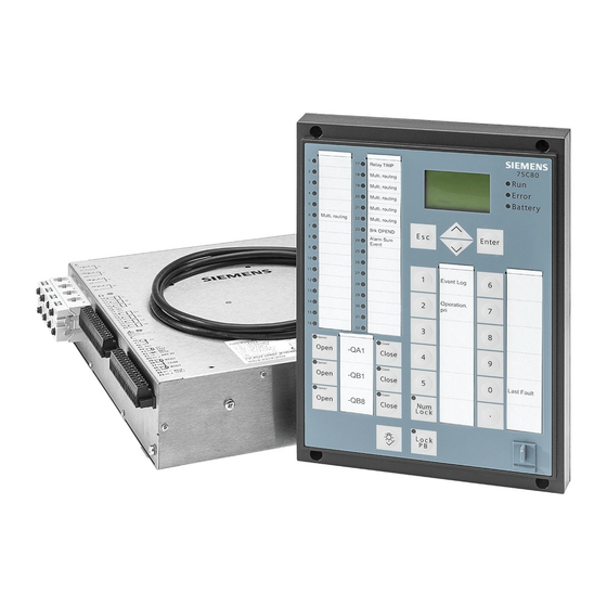
User Manuals: Siemens 7SC80 Protection Controller
Manuals and User Guides for Siemens 7SC80 Protection Controller. We have
3
Siemens 7SC80 Protection Controller manuals available for free PDF download: Manual
Siemens 7SC80 Manual (782 pages)
SIPROTEC Compact Feeder Protection and Recloser Controller
Brand:
Siemens
| Category:
Controller
| Size: 24.59 MB
Table of Contents
Preface
3
Technical Data
3
Open Source Software
9
Table of Contents
11
1 Introduction
21
Overall Operation
22
Application Scope
25
Characteristics
27
2 Functions
33
General
34
Functional Scope
34
Description
34
Setting Notes
34
Settings
36
Device, General Settings
39
General Device Functions
39
Setting Notes
41
Settings
46
Information List
47
Power System Data 1
48
Description
48
Setting Notes
49
Settings
57
Information List
61
Oscillographic Fault Records
61
Description
62
Setting Notes
62
Settings
63
Information List
63
Settings Groups
63
Description
63
Setting Notes
63
Settings
64
Information List
64
Power System Data 2
65
Description
65
Setting Notes
65
Settings
68
Information List
69
EN100-Module
69
Description
69
Information List
70
Overcurrent Protection 50, 51, 50N, 51N
71
General
71
Definite Time, High-Set Elements 50-3, 50-2, 50N-3, 50N-2
71
Definite Time Overcurrent Elements 50-1, 50N-1
72
Inverse Time Overcurrent Elements 51, 51N
74
Inverse Time Overcurrent Elements 51-1, 51-2, 51-3, 51-4 and 51N-1, 51N-2, 51N-3, 51N-4
78
Inverse Time Overcurrent Protection 51V (Voltage-Controlled/Voltage-Restraint)
81
Special Variant Function 50-1, 50N-1 for Service Interlocking
84
Dynamic Cold Load Pickup Function
85
Inrush Restraint
85
Pickup Logic and Tripping Logic
85
Two-Phase Overcurrent Protection (Only Non-Directional)
87
Setting Notes
87
Settings
96
Information List
107
Directional Overcurrent Protection 67, 67N
111
General
111
Directional Definite Time High-Current Elements 67-2, 67-3, 67N-2 and 67N-3
112
Definite Time, Directional Time Overcurrent Elements 67-1, 67N-1
113
Inverse Time, Directional Time Overcurrent Elements 67-TOC, 67N-TOC
115
Inverse Time, Directional Time Overcurrent Elements 67-TOC-1, 67-TOC-2, 67- TOC-3, 67-TOC-4 and 67N-TOC-1, 67N-TOC-2, 67N-TOC-3, 67N-TOC-4
117
Interaction with Voltage Monitoring
121
Dynamic Cold Load Pickup Function
121
Inrush Restraint
121
Determination of Direction
121
Setting Notes
125
Settings
134
Information List
147
Dynamic Cold Load Pickup
151
Description
151
Setting Notes
153
Settings
157
Information List
165
Single-Phase Overcurrent Protection
166
Description
166
High-Impedance Ground Fault Unit Protection
167
Tank Leakage Protection
169
Setting Notes
170
Settings
175
Information List
186
Voltage Protection 27, 59
187
Measurement Principle
187
Overvoltage Protection 59
189
Undervoltage Protection 27
189
Displacement Voltage Protection
192
Setting Notes
194
Settings
198
Information List
199
47 Negative Phase Sequence Overvoltage
202
Description
202
Setting Notes
202
Settings
203
Information List
203
27/59 Under/Over Voltage for VX
204
Description
204
Setting Notes
205
Settings
206
Information List
207
Negative Sequence Protection 46
208
Definite Time Characteristic
208
Inverse Time Characteristic 46-TOC
208
Setting Notes
211
Settings
213
Information List
214
Frequency Protection 81 O/U
215
Description
215
Setting Notes
216
Settings
217
Information List
218
Thermal Overload Protection 49
219
Monitoring of the Thermal Condition, for Example at Transformers
219
Setting Notes
221
Settings
223
Information List
224
Monitoring Functions
225
Measurement Supervision
225
General
225
Hardware Monitoring
225
Software Monitoring
227
Monitoring of the Transformer Circuits
227
Broken Conductor Detection
229
Inrush-Current Detection
231
Current and Voltage Transformer Monitoring
234
Setting Notes
236
Settings
240
Information List
241
Trip Circuit Supervision 74TC
242
Description
243
Setting Notes
245
Settings
246
Information List
246
Malfunction Responses of the Monitoring Functions
246
Description
246
Ground Fault Protection 64, 67N(S), 50N(S), 51N(S)
248
Ground Fault Detection for Cos-Φ-/Sin-Φ Measurement (Standard Method)
248
Ground Fault Detection for V0/I0-Φ Measurement
254
Ground Fault Location
258
Setting Notes
259
Settings
265
Information List
267
Automatic Reclosing System 79
269
Program Execution
269
Blocking
273
Status Recognition and Monitoring of the Circuit Breaker
274
Controlling Protection Elements
275
Zone Sequencing / Fuse Saving Scheme
277
Setting Notes
278
Settings
283
Information List
302
Sectionalizer Function
304
Functional Description
304
Setting Notes
306
Settings
307
Information List
308
Triple Single Mode
309
Overview
309
Setting Notes
309
Settings
311
Information List
311
Fault Locator
314
Description
314
Setting Notes
315
Settings
316
Information List
316
Breaker Failure Protection 50BF
317
Description
317
Setting Notes
320
Settings
321
Information List
322
Flexible Protection Functions
323
Description
323
Setting Notes
329
Settings
333
Information List
335
Synchrocheck
337
General
337
Functional Sequence
338
De-Energized Switching
340
Direct Command / Blocking
340
Interaction with Control, Automatic Reclosing and External Control
341
Setting Notes
342
Settings
345
Information List
346
Capacitor Control
348
Modes of Operation
348
Setting Notes
348
Settings
350
Information List
350
Tap Changer
351
General
351
Setting Notes
351
Settings
353
Information List
354
Recloser Capacitor Test
355
General
355
Setting Notes
357
Settings
357
Information List
357
Phase Rotation
358
Description
358
Setting Notes
358
Function Logic
359
Pickup Logic of the Entire Device
359
Tripping Logic of the Entire Device
359
Auxiliary Functions
361
Message Processing
361
Leds and Binary Outputs (Output Relays)
361
Information Via Display Panel or PC
361
Information to a Substation Control Center
362
Statistics
363
Description
363
Circuit Breaker Maintenance
363
Setting Notes
369
Information List
371
Measurement
372
Display of Measured Values
372
Transmitting Measured Values
373
Information List
374
Average Measurements
376
Description
376
Setting Notes
376
Settings
376
Information List
376
Min/Max Measurement Setup
377
Description
377
Setting Notes
377
Settings
377
Information List
377
Set Points for Statistic
379
Description
379
Setting Notes
380
Information List
380
Energy Metering
380
Description
380
Settings
380
Commissioning Aids
381
Description
381
Breaker Control
383
Control Device
383
Description
383
Information List
384
Types of Commands
384
Description
384
Command Sequence
384
Description
385
Interlocking
385
Command Logging
394
Description
394
Notes on Device Operation
395
Web Monitor
395
Operation Panel of the Device
402
Recloser Setting Summary
403
Description
403
Setting Notes
403
Additional Applications with 6 Voltage Inputs
425
General
425
Description
425
Setting Notes
425
Settings
425
Voltage Protection 27, 59 of Side 2
427
Overview Voltage Protection of Side 2
427
Measurement Principle
427
Overvoltage Protection 59 of Side 2
428
Undervoltage Protection 27 of Side 2
429
Setting Notes
432
Settings
436
Information List
437
Frequency Protection 81 O/U of Side 2
438
Description
438
Setting Notes
440
Settings
441
Information List
442
Voltage-Transformer Supervision of Side 2
442
Description
442
Setting Notes
445
Settings
446
Information List
446
3 Mounting and Commissioning
449
Mounting and Connections
450
Configuration Information
450
Hardware Modifications
453
Disassembly
453
Current Terminal Connections
459
Process Terminal Connections
460
Interface Modules
460
Reassembly
461
Installation
461
General
461
HMI (Human-Machine Interface) Optional
463
Checking Connections
471
Checking the Data Connections of the Interfaces
471
Checking the System Connections
475
Commissioning
477
Test Mode and Transmission Block
478
Testing the System Interface (at Port F)
478
Communication Module Configuration
480
Checking the Status of Binary Inputs and Outputs
483
Tests for Breaker Failure Protection
485
Testing User-Defined Functions
487
Current, Voltage, and Phase Rotation Testing
487
Test for High Impedance Protection
488
Testing the Reverse Interlocking Scheme
488
Direction Check with Load Current
489
Polarity Check for Voltage Input VX
490
Ground Fault Check
491
Polarity Check for Current Input Ι
492
Switching Test for Configured Equipment
495
Creating a Test Fault Record
495
Password Security
496
Final Preparation of the Device
498
4 Technical Data
499
General Device Data
500
Analog Inputs
500
Auxiliary Voltage
501
Binary Inputs and Outputs
502
Communication Interfaces
503
Electrical Tests
504
Mechanical Tests
506
Climatic Stress Tests
506
Service Conditions
507
Constructive Design
507
UL Certification Conditions
508
Definite-Time Overcurrent Protection 50, 50N
509
Inverse-Time Overcurrent Protection
511
Directional Overcurrent Protection 67, 67N
527
Inrush Restraint
529
Dynamic Cold Load Pickup
530
Single-Phase Overcurrent Protection
531
Voltage Protection 27, 59
532
Negative Phase Sequence Overvoltage Protection
534
Voltage Protection for VX
535
Negative Sequence Protection 46-1, 46-2 (Definite Time Characteristic)
536
Negative Sequence Protection 46-TOC (Inverse Time Characteristic)
537
Frequency Protection 81
543
Thermal Overload Protection
544
Ground Fault Detection (Sensitive/Insensitive)
546
Automatic Reclosing Function
553
Sectionalizer
554
Fault Locator
556
Breaker Failure Protection 50BF
557
Flexible Protection Functions
558
Synchronization Function
561
User-Defined Functions (CFC)
563
Additional Functions
572
Switching Device Control
576
Additional Applications with 6 Voltage Inputs
577
Voltage Protection 27, 59 of Side 2
577
Frequency Protection 81 of Side 2
578
Dimensions
580
Feeder Protection and Recloser Controller 7SC80
580
Hmi
581
Varistor
581
A Ordering Information and Accessories
583
Ordering Information 7SC802
584
Ordering Information 7SC803
587
Accessories
590
A.3 Accessories
590
B Terminal Assignments
591
7SC80 - Housing for Cabinet Flush Mounting and Cabinet Surface Mounting
592
C Connection Examples
599
Connection Examples for Current and Voltage Transformers
600
D Current Transformer Requirements
605
Accuracy Limiting Factors
606
Class Conversion
607
D.2 Class Conversion
607
E Default Settings and Protocol-Dependent Functions
609
Leds
610
E.1 Leds
610
Binary Input
611
E.2 Binary Input
611
Binary Output
612
E.3 Binary Output
612
Function Keys
613
E.4 Function Keys
613
Default Display
614
E.5 Default Display
614
Protocol-Dependent Functions
616
F Functions, Settings, Information
617
Functional Scope
618
Settings
621
Information List
694
Group Alarms
759
Measured Values
761
Literature
767
Glossary
769
Index
779
Advertisement
Siemens 7SC80 Manual (340 pages)
Feeder Automation Controller
Brand:
Siemens
| Category:
Controller
| Size: 16.53 MB
Table of Contents
Table of Contents
9
Introduction
15
Overall Operation
16
Application Scope
18
Characteristics
20
Functions
23
General
24
Functions Overview
24
Description
24
Setting Notes
24
Settings
26
Device, General Settings
28
General Device Functions
28
Battery Charger
29
Setting Notes
31
Settings
32
Information List
33
Power System Data 1
35
Description
35
Setting Notes
35
Settings
40
Information List
41
Oscillographic Fault Records
42
Description
42
Setting Notes
43
Settings
44
Information List
44
Settings Groups
45
Setting Notes
45
Settings
46
Information List
46
Power System Data 2
47
Description
47
Setting Notes
47
Settings
51
Information List
52
EN100-Module
53
Description
53
Information List
53
Overcurrent Protection 50, 51, 50N, 51N
54
General
54
Definite Time, High-Set Elements 50-3, 50-2, 50N-3, 50N-2
55
Definite Time Overcurrent Elements 50-1, 50N-1
57
Inrush Restraint
60
Pickup Logic and Tripping Logic
63
Setting Notes
63
Settings
68
Information List
69
Directional Overcurrent Protection 67, 67N
71
General
71
Definite Time, Directional High-Set Elements 67-2, 67N-2
73
Definite Time, Directional Time Overcurrent Elements 67-1, 67N-1
75
Interaction with Fuse Failure Monitor (FFM)
77
Inrush Restraint
77
Determination of Direction
77
Setting Notes
82
Settings
86
Information List
88
Voltage Protection 27, 59
89
Measurement Principle
89
Overvoltage Protection 59
91
Undervoltage Protection 27
92
Setting Notes
96
Settings
100
Information List
101
27/59 Under/Over Voltage for VX
103
Function Description
103
Setting Notes
104
Settings
106
Information List
106
Negative Sequence Protection 46
107
Definite Time Characteristic
107
Inverse Time Characteristic 46-TOC
108
Setting Notes
110
Settings
114
Information List
114
Frequency Protection 81 O/U
115
Description
115
Setting Notes
116
Settings
118
Information List
119
Monitoring Functions
120
Measurement Supervision
120
General
120
Hardware Monitoring
120
Software Monitoring
122
Monitoring of the Transformer Circuits
123
Measurement Voltage Failure Detection
125
Setting Notes
128
Settings
130
Information List
131
Malfunction Responses of Monitoring Equipment
132
Description
132
Fault Locator
134
Description
134
Setting Notes
135
Settings
136
Information List
136
Breaker Failure Protection 50BF
137
Description
137
Setting Notes
140
Settings
142
Information List
142
Phase Sequence Reversal
143
Description
143
Setting Notes
144
Flexible Protection Functions
145
Description
145
Setting Notes
149
Settings
153
Information List
155
Function Control
156
Pickup Logic of the Entire Device
156
Tripping Logic of the Entire Device
156
Additional Functions
158
Message Processing
158
Leds and Binary Outputs (Output Relays)
158
Information Via Display Panel or PC
159
Information to a Substation Control Center
160
Statistics
160
Description
160
Setting Notes
160
Information List
161
Measurement
161
Display of Measured Values
162
Transmitting Measured Values
163
Information List
164
Average Measurements
165
Description
165
Setting Notes
165
Settings
166
Information List
166
Min/Max Measurement Setup
167
Description
167
Setting Notes
167
Settings
167
Information List
168
Set Points for Measured Values
170
Setting Notes
170
Set Points for Statistic
170
Description
170
Information List
171
Energy Metering
171
Description
171
Setting Notes
171
Settings
171
Information List
172
Commissioning Aids
172
Description
173
Command Processing
174
Control Device
174
Description
174
Information List
175
Command Types
175
Description
175
Command Sequence
176
Description
176
Switchgear Interlocking
177
Description
177
Command Logging
184
Description
184
Device Operation
185
Web Monitor
185
Mounting and Commissioning
197
Mounting and Connections
198
Configuration Information
198
Hardware Modifications
200
Disassembly
200
Current Terminal Connections
204
Process Terminal Connections
205
Interface Modules
206
Reassembly
207
Installation
208
General
208
Checking Connections
210
Checking the Data Connections of the Interfaces
210
Checking the System Connections
213
Battery Charging Function
215
Commissioning
216
Test Mode and Transmission Block
217
Testing the System Interface (at Port F)
217
Communication Module Configuration
219
Checking the Status of Binary Inputs and Outputs
220
Tests for Breaker Failure Protection
222
Testing User-Defined Functions
224
Current, Voltage, and Phase Rotation Testing
224
Testing the Reverse Interlocking Scheme
225
Direction Check with Load Current
226
Polarity Check for Current Input I N
227
Switching Test for Configured Equipment
229
Creating a Test Fault Record
230
Final Preparation of the Device
231
Technical Data
233
General Device Data
234
Analog Inputs
234
Auxiliary Voltage
234
Binary Inputs and Outputs
235
Communication Interfaces
236
Electrical Tests
237
Mechanical Tests
239
Climatic Stress Tests
240
Service Conditions
240
Constructive Design
241
UL Certification Conditions
241
Definite-Time Overcurrent Protection 50, 50N
242
Directional Overcurrent Protection 67, 67N
244
Inrush Restraint
246
Voltage Protection 27, 59
247
Voltage Protection for VX
249
Negative Sequence Protection 46-1, 46-2 (Definite Time Characteristic)
250
Negative Sequence Protection 46-TOC (Inverse Time Characteristic)
251
Frequency Protection 81
257
Fault Locator
258
Breaker Failure Protection 50BF
259
Flexible Protection Functions
260
User-Defined Functions (CFC)
263
Additional Functions
269
Switching Device Control
273
Dimensions
274
Feeder Automation Controller 7SC80
274
Appendix
275
Ordering Information and Accessories
276
Ordering Information
276
7Sc80 V4.6
276
Accessories
278
Terminal Assignments
279
7SC80 - Housing for Cabinet Flush Mounting and Cabinet Surface Mounting
279
Connection Examples
281
Current Transformer Requirements
284
Accuracy Limiting Factors
284
Effective and Rated Accuracy Limiting Factor
284
Calculation Example According to IEC 60044-1
284
Class Conversion
285
Default Settings
286
Leds
286
Binary Input
287
Binary Output
287
Function Keys
288
Default Display
289
Protocol-Dependent Functions
291
Functional Scope
292
Settings
294
Information List
303
Group Alarms
318
Measured Values
319
Literature
323
Glossary
325
Index
337
Siemens 7SC80 Manual (32 pages)
Brand:
Siemens
| Category:
Control Unit
| Size: 0.31 MB
Table of Contents
Preface
3
Table of Contents
7
DNP3 TCP Device Profile
9
Data Objects Implementation
10
DNP3 TCP Device Profile Documents
13
Point Lists
19
Binary Input Points
20
Control Relay Output Blocks/Binary Output Status
24
Counters
25
Analog Inputs
26
Flexible Mapping
29
Index
31
Advertisement
Advertisement
Related Products
Siemens 7SR224
Siemens siprotec 7SA6
Siemens 7sg15 microtapp
Siemens 72EG34AFP
Siemens 72HG34AFP
Siemens 72JG34AFP
Siemens 72MG34AFP
Siemens 72NG34AFP
Siemens 72PG34AFP
Siemens 72RG32AFP
Siemens Categories
Industrial Equipment
Controller
Control Unit
Oven
Washer
More Siemens Manuals
Login
Sign In
OR
Sign in with Facebook
Sign in with Google
Upload manual
Upload from disk
Upload from URL