Sign In
Upload
Manuals
Brands
Siemens Manuals
Media Converter
6RA8085-6FV62
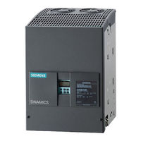
Siemens 6RA8085-6FV62 DC Converter Manuals
Manuals and User Guides for Siemens 6RA8085-6FV62 DC Converter. We have
1
Siemens 6RA8085-6FV62 DC Converter manual available for free PDF download: Operating Instructions Manual
Siemens 6RA8085-6FV62 Operating Instructions Manual (759 pages)
Brand:
Siemens
| Category:
Media Converter
| Size: 35.29 MB
Table of Contents
Legal Information
4
Product Name
5
Technical Support
7
Spare Parts
7
General Safety Instructions
19
Hearing Protection
23
ESD-Sensitive Components
24
Industrial Security
25
Residual Risks of Power Drive Systems
26
Ordering Information for Options and Accessories
32
Ordering Information for Accessories
34
Area of Application
37
Additional Components
38
Extended Functions
39
Technical Data
41
Environmental Requirements
46
Ambient Temperature
46
Transportation, Unpacking
79
Installation
79
Dimension Drawings
82
Installing Options and Accessories
91
AOP30 Operator Panel
91
Basic Information about EMC
94
EMC Planning
97
General Information
97
Shield Connection
103
Block Diagram with Connection Suggestion
116
Power Connections
125
Field Supply
145
Line Reactors
148
Power Unit
171
Electronics Power Supply
175
Open-Loop and Closed-Loop Control Section
177
Parallel Interface
185
Memory Card Slot
187
Additional System Components
193
DRIVE-Cliq Interface
193
Option Board: Communication Board Ethernet CBE20
194
Safety Instructions
194
Interface Description
195
Mac Address
195
X1400 Ethernet Interface
196
Meaning of the Leds
197
Installation
199
Technical Data
199
X500 DRIVE-Cliq Interface
201
X524 Electronics Power Supply
201
X520 Encoder System Interface
202
Connection Example
203
Dimension Drawing
204
Sensor Module Cabinet-Mounted SMC30
208
Safety Instructions
209
Connection Examples
216
Dimension Drawing
219
Protective Conductor Connection and Shield Support
221
Technical Data
222
Terminal Module TM15
226
Safety Instructions
226
Interface Description
227
Terminal Type
228
Connection Example
231
Cause and Rectification of Faults
232
Dimension Drawing
233
Installation
233
Protective Conductor Connection and Shield Support
235
Technical Data
237
Terminal Module TM31
239
Safety Instructions
240
Interface Description
241
Terminal Type
242
X521 Analog Inputs
245
X522 Analog Outputs/Temperature Sensor
246
X541 Bidirectional Digital Inputs/Outputs
248
X542 Relay Outputs
249
Dimension Drawing
252
Installation
253
Protective Conductor Connection and Shield Support
254
Technical Data
256
Terminal Module TM150
257
Installation
267
Commissioning Checklist
272
Mechanical Installation
272
Electrical Installation
273
Restoring the Factory Settings
273
Commissioning Using the BOP20 Operator Panel
275
Commissioning Steps
276
Access Authorization
276
Field Weakening
280
First Commissioning
283
Selecting the Language
284
Encoder Selection
286
Optimization Runs
288
Status after Commissioning
288
Resetting Parameters to Factory Settings
289
Commissioning with the STARTER Commissioning Tool
289
Installing the STARTER Commissioning Tool
290
Procedure for Commissioning with STARTER
291
Basic Procedure When Using STARTER
291
Creating the Project
291
The STARTER Project Wizard
293
Configuring a Drive Unit
300
Brake Control
307
Activating Function Modules
323
Drive Optimization
338
Quick Commissioning
338
Manual Optimization
346
Optimizing the Speed Controller
349
Controller Optimization
350
Operation
351
Basic Information
351
Parameter Categories
352
Resetting Parameters
353
Access Level
354
CDS: Command Data Set
355
Using Data Sets
358
Drive Objects
359
Memory Card Functions
361
Important Parameters
365
BICO Technology: Interconnecting Signals
366
Binectors, Connectors
367
Interconnecting Signals Using BICO Technology
368
Internal Encoding of the Binector/Connector Output Parameters
369
Parameterizing Using the BOP20 (Basic Operator Panel 20)
370
Operation
371
Displays and Using the BOP20
375
Status Display
375
Parameter Display
376
Value Display
377
Displaying Faults and Alarms
380
Controlling the Drive Using the BOP20
381
Menu: Operation Screen
385
Setting Options
385
Parameterization Menu
386
Menu: Fault/Alarm Memory
387
Menu: Commissioning/Service
388
Drive Commissioning
388
Device Commissioning
389
AOP Settings
389
Setting the Date/Time
392
Date Format
393
Sprachauswahl/Language Selection
395
Operation Via the Operator Panel (LOCAL Mode)
395
LOCAL/REMOTE Key
395
CCW/CW Changeover
397
Increase Setpoint/Decrease Setpoint
397
AOP Setpoint
398
Timeout Monitoring
399
Saving the Parameters Permanently
403
Parameterization Errors
403
Descriptions of Functions
405
Overview of Inputs/Outputs
405
Digital Inputs/Outputs
405
Analog Inputs
406
Function Diagrams
406
Analog Outputs
407
Communication, IT Security
407
Communication According to Profidrive
407
Communication Services
408
Application Classes
410
Cyclic Communication
412
Telegrams and Process Data
412
Structure of the Telegrams
414
Description of Control Words and Setpoints
415
Overview of Control Words and Setpoints
415
Central Control and Status Words
435
Diagnostics Channels for Cyclic Communication
438
Parallel Operation of Communication Interfaces
440
General Information about Acyclic Communication
443
Structure of Orders and Responses
445
Determining the Drive Object Numbers
451
Example 1: Read Parameters
451
Task Description
451
Basic Procedure
452
Communication Via PROFIBUS DP
457
PROFIBUS Connection
457
Bus Connector
458
Bus Terminating Resistor
458
General Information about PROFIBUS
459
Commissioning PROFIBUS
463
Setting the PROFIBUS Interface
463
Setting the PROFIBUS Address
463
PROFIBUS Interface in Operation
464
Device Identification
465
Diagnostics Options
466
SIMATIC HMI Addressing
466
Monitoring, Telegram Failure
468
Direct Data Exchange
470
Setpoint Assignment in the Subscriber
472
Commissioning of the PROFIBUS Slave-To-Slave Communication
474
GSD During Operation
483
Messages Via Diagnostics Channels
484
Communication Via PROFINET IO
487
General Information about PROFINET IO
493
Real-Time (RT) and Isochronous Real-Time (IRT) Communication
494
Ip Address Assignment
495
Data Transmission
496
Communication Channels for PROFINET
498
Drive Control with PROFINET
498
PROFINET Interfaces
498
Media Redundancy
501
RT Classes for PROFINET IO
501
Topology Rules
506
Profinet Gsdml
507
Communication with CBE20
507
Communication Via SINAMICS Link
514
Basic Principles of SINAMICS Link
514
Transmission Time
515
Configuring and Commissioning
517
Sending Data
518
Receiving Data
520
Communication Failure When Booting or in Cyclic Operation
524
Function Diagrams and Parameters
526
Writing and Reading Parameters with Class 4Xx
538
Mapping Tables
542
Communication Details
548
Communication Sequence
551
Messages and Parameters
552
Specification
553
Function Diagrams
553
Switch On, Switch Off, Enable
554
Safety Shutdown (E-STOP)
559
Setpoint Channel
560
Ramp-Function Generator
560
Control Signals
562
Ramp-Function-Generator Tracking
564
Fixed Setpoint
567
Encoder Evaluation
568
General Information
568
Control and Status Words for Encoders
570
Speed Controller
570
Technology Controller
577
Commissioning with STARTER
578
Operating Hours Counter
583
Speed-Dependent Current Limitation
590
Overview of Functions
593
Configuring for Dynamic Overload Capability
594
Automatic Restart
600
Topology Overview
602
Standard Mode
606
Parameter Assignment
609
12-Pulse Parallel Connection
611
Operating Modes
614
12-Pulse Series Connection
618
12-Pulse Series Connection: Controlled Converter + Uncontrolled Converter
620
Switchover of the Power Unit Topology - Option S50
621
Direction of Rotation Reversal Using Field Reversal
622
General Information
626
Series Connection
628
Parallel Connection
629
Bus Connection
630
Terminal Module Cabinet TMC (Option G63)
633
Runtime (Operating Hours Counter)
633
Diagnostic Memory
634
Thyristor Diagnostics
635
Description of the Leds on the CUD
637
Diagnostics Via STARTER
640
Diagnostic Functions
640
Function Generator
641
Trace Function
644
Single Trace
644
Acknowledging Faults
652
Fault Buffer
653
Configuring Messages
656
Parameters and Function Diagrams for Faults and Alarms
658
Forwarding Faults and Alarms
659
Maximum Configuration
661
Free Function Blocks
663
General Remarks
663
Write and Know-How Protection
671
Deactivating Write Protection
673
Know-How Protection
673
Activating Know-How Protection
677
Deactivating Know-How Protection
679
Changing the Password
680
Overview of Important Parameters
685
Maintenance
687
Upgrading the Device Firmware
689
Step 1: Backup the Configuration
689
Replacing Components
694
Replacing the Fan
694
Replacing Fuses
700
Functional Safety
711
Application Examples
716
Description of the Applications
716
Diagnostics Test
724
Recommended Safety Relays
730
Certifications and Standards
731
Reference Standards
733
Country-Specific Standards
733
List of Abbreviations
734
Environmental Compatibility
742
Advertisement
Advertisement
Related Products
Siemens 6RA8085-6DS22
Siemens 6RA8085-6FS22
Siemens 6RA8085-6GS22
Siemens 6RA8085-6DV62
Siemens 6RA8085-6GV62
Siemens 6RA8088-6LS22
Siemens 6RA8082-6FV62
Siemens 6RA8088-6LV62
Siemens 6RA8087-6GV62
Siemens 6RA8081-6GV62
Siemens Categories
Industrial Equipment
Controller
Control Unit
Oven
Washer
More Siemens Manuals
Login
Sign In
OR
Sign in with Facebook
Sign in with Google
Upload manual
Upload from disk
Upload from URL