Sign In
Upload
Manuals
Brands
Honeywell Manuals
Heater
SYA14 Series
Honeywell SYA14 Series Manuals
Manuals and User Guides for Honeywell SYA14 Series. We have
1
Honeywell SYA14 Series manual available for free PDF download: Manual
Honeywell SYA14 Series Manual (737 pages)
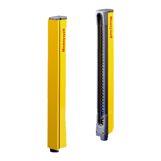
Safety Light Curtains
Brand:
Honeywell
| Category:
Heater
| Size: 14.6 MB
Table of Contents
Ff-Sb Installation Manual 7Deoh Ri Frqwhqw
86
Table of Contents
86
Organization of Installation Manual
87
Introduction
87
Important Highlighted Information
87
Overview
87
Organization of Installation Manual (Cont'D)
88
Warranty and Remedy
88
Sales and Service
88
Light Curtain Identification
89
Overview
91
Machine Guarding and Perimeter Protection
91
Approvals
94
Standards Compliance
95
Regulations Compliance
95
Directives Compliance
96
Control Reliability
96
Operation
97
Scanning Range
99
Indicators
100
Mirrors
101
Specifications
103
Light Curtain Order Guide
104
Mirror and Mounting Bracket Order Guide
106
Replacement Part Order Guide
106
Overview
109
How to Calculate Safety Distance
110
How to Calculate Safety Distance (Reflective Surfaces Considered)
112
Emitter and Receiver Dimensions
113
Mounting Considerations
114
Mounting Hardware
120
Overview
127
Power Wiring
128
Test Contacts
130
Factory Settings (Receivers Only)
130
Cycle Start Mode
131
Wiring Diagrams
131
Overview
137
Operational Test
137
Troubleshooting Procedures
138
Cleaning
142
Section 2
166
Control Reliability
168
Important Highlighted Information
168
Important Information
168
Organization of Installation Manual
168
Overview
168
Read and Understand this Instruction Manual
168
Compliance
169
European Directives Compliance
169
European Regulations Compliance
169
Product Approval
169
Selection, Installation and Use Considerations
170
United States Regulations Compliance
170
United States Standards Compliance
170
Additional Protection
171
Control and Sensing Unit
172
Description
172
Description and Operation
172
Overview
172
Unit Compatibility
172
Unit Identification Plates
173
Operation
174
Specifications
174
Protection Height
175
Resolution
175
Installation
176
Overview
176
Machine Guarding Protection
177
How to Calculate Safety Distance
178
Normal Approach Point-Of-Operation Guarding
178
Parallel Approach Point-Of-Operation Guarding
180
Angular Approach Point-Of-Operation Guarding
181
Reflective Surfaces
181
Mounting Considerations
182
Optical Alignment Procedure
182
Mounting Dimensions
184
Electrical Connection
188
Overview
188
Connecting Sensing Units to Control Units
189
Connecting Machine Stop Control Outputs ( Main out 1 and Main out 2)
190
Electrical Power and the Control Unit
190
Connecting Indicator Lamps to Auxiliary Terminals
191
Connecting the Test Input
192
Setting the Mode of Operation
192
Example Electrical Wiring Connections
193
Inspection
196
Inspection and Maintenance
196
Scheduled Machine Inspection
196
Scheduled Safety Light Curtain Inspection
196
Control Unit Status Indicators
197
Troubleshooting
198
Fuse Replacement
200
Repair
200
Complete Product Set Order Guides
202
Order Guides
202
Replacement Part and Accessories Order Guides
202
Customer Service Information
204
Index
204
Sales and Service
204
Warranty and Remedy
204
Declaration of Conformity
208
Section 3
212
Important Information
214
Organisation of Installation Manual
214
Overview
214
Control Reliability
215
Important Highlighted Information
215
Approvals
216
European Directives Compliance
216
European Standards Compliance
216
Safety Laser Scanner Installation and Use
216
United States Regulations Compliance
217
United States Standards Compliance
217
Additional Protection
218
Glossary
220
Setting the Zones
220
Others
221
Outputs
221
Targets
221
Description and Operation
222
General
222
Overview
222
Rinciple of Operation
222
Sensor Construction
224
Technical Specifications
227
Minimum Distance to Obstacles
228
Installation and Mounting
230
Material Required for Installing the Ff-Se
230
Mounting
230
Operating Precautions
230
Overview
230
Statutory Mounting and Operating Provisions
234
Example of Stationary Application
235
Sensor Accuracy / Safety Margin
235
Application on a Automatic Guide Vehicule (AGV)
236
Example of Application for AGV
239
Electrical Connections
240
Integrating Ff-Se Signals into Machine Control
240
Overview
240
Connecting the Power Supply and the Signal Cable
243
Connecting the Interface Cable
245
Checking the Monitoring Functions
246
Defining the Protection Zones
246
Access Authorisation
247
Daily Maintenance
248
Maintenance and Trouble Shooting
248
Maintenance Procedures
248
Overview
248
Six-Month Maintenance
248
Ff-Se Replacement Procedure
249
Transport and Storage
249
Troubleshooting
251
Order Guide
256
Sales and Service
256
Warranty and Remedy
256
Warranty Information
256
Appendix
258
Mechanical Dimensions (MM / In) : for Reference Only
258
Cable Wiring
259
Declaration of Conformity
260
Section 4
265
Important Information
269
Organization of Installation Manual
269
Overview
269
Control Reliability
270
Important Highlighted Information
270
Approvals
271
Conformity to European Directives
271
European Directives Compliance
271
European Standards Compliance
271
Safety Mat Installation and Use
271
Additional Protection
272
United States Regulations Compliance
272
Description and Operation
276
Mat Identification
276
Theory of Operation
276
Mat Specifications
280
Control Unit Specifications
281
Installation
284
Machine Guarding Protection
284
Point-Of-Operation Guarding
285
Safety Distances
285
Safety Distance Example One (Point-Of-Operation Guarding)
288
Transport and Storage
290
Use and Installation Considerations
290
Reference Floor Flatness and Rigidity Considerations
291
Fiber Optic Cable Considerations
292
Connector Considerations
293
On Floor Installation
295
Safety Mat Installation
295
In Floor Installation
296
Area Controlled by Several Safety Mats Via a Single Control Unit
298
Serial Connection of Several Safety Mats
298
Area Controlled by Several Safety Mats Run by Several Control Units
300
Determining the Number of Safety Mats Controlled by a Control Unit
300
Mounting Dimensions (for Reference Only)
301
Connections and Setup
305
Overview
305
Fiber Optic Cable Connection to the Control Unit
306
Fiber Optic Connections
306
Fiber Optic Cable Connection to the Connecting Box
307
ST Connector with the Cable-To-Cable Connector
307
Electrical Connections
308
Overview
308
Permanent Self-Checking (Monitoring)
310
Final Switching Device (FSD) Monitoring
313
Overview
313
Test Input
314
Physical Configuration and Wiring Diagram Examples
315
Excess Gain Adjustment after Installation
320
Setup
320
Indicator Status
322
Sensing Threshold Indicator (See Figure 3-15)
322
Excess Gain Adjustment During Operation
323
Inspection and Maintenance
325
Operational Test
325
Overview
325
Important Information
326
Inspection
326
Fuse Replacement
327
Maintenance
327
Indicator Status and Corrective Actions
328
Troubleshooting Flow Diagram (Sheet 1 of 2)
329
Troubleshooting Flow Diagram (Sheet 2 of 2)
330
Cable Extension Order Guide
331
Order Guides
331
Safety Mat Order Guide
331
Control Unit Order Guide
332
Accessories and Spare Parts Order Guide
333
Edge Trim Order Guide
333
Sales and Service
335
Warranty and Remedy
335
Warranty Information
335
Index
337
Declaration of Conformity
339
Section 5
342
Overview
344
Control Reliability
346
Directives Compliance
346
Organization of Manual
347
Overview
348
Operation
351
Detection
352
Response Times
352
Scan Range
353
Indicators
354
Indicator Status
356
Mirrors
357
Specifications
359
Overview
360
How to Calculate Safety Distance
361
Sample Calculation
362
Reflective Surfaces Considered
363
Mounting Considerations
364
Sample Calculation
364
Optical Alignment
365
Side by Side or Multiple System Installation
366
Emission Frequency Selection
367
Start and Restart (Cycle) Interlock Mode of Operation
369
Test Input Option
370
Mounting Hardware
371
Mirror Hardware
372
Overview
375
Quick-Connect Style
375
Terminations
375
Quick-Connect Connector Wiring
376
Terminal Strip Connector Wiring
377
Power Supply Wiring
380
Perimeter System Wiring
381
Inspection and Maintenance
383
Operational Test
383
Overview
383
Troubleshooting Procedures
384
Cleaning
387
Interchangeability
387
Maintenance and Repair
387
Fuse Replacement
390
Ground Connection
391
Emission Frequency Selection
394
Order Guide
397
Order Guides
397
Sample Order
398
Warranty Information
399
Warranty and Remedy
429
Sales and Service
437
Section 6
468
50FY Series Hall Effect
469
Door Interrupt System, EN954 Category III
469
Installation Instructions for the
469
Instrucciones de Instalación para el
475
Sistema Interruptor de Puerta por Efecto Hall
475
Instructions D'installation Pour Le
481
Système de Détection de Proximité de Passage de Porte, EN954 Catégorie III, Série 50FY À Effet Hall
481
Einbau-Anweisungen für das
487
Halleffekt-Türverriegelungssystem der Serie 50FY, en 954 Kategorie III
487
Istruzioni Per L'installazione del
493
Sistema DI Interruzione Porte
493
Installatie-Instructies Voor Het Hall-Effect Deuronderbrekingssysteem Van de
499
Serie 50FY, EN954 Categorie III
499
Efeito Hall, Série 50FY, EN954 Categoria III
505
Instruções para Instalação Do
505
Sistema de Detecção de Abertura de Porta Com
505
EN954, Kategori III
511
Installationsanvisning Til
511
Model 50FY Halleffektafbryder Til Låger
511
50FY-Sarjan Hall-Katkaisujärjestelmälle Ovia
517
Asennusohjeet
517
Varten, EN954 Luokka III
517
50FY-Seriens Halleffektbrytsystem För Dörrar
523
EN954, Kategori III
523
Installationsanvisningar För
523
Ïäçãßåò Åãêáôüóôáóçò Ãéá Ôï Óýóôçìá Äéáêïðþò Èýñáò Hall Effect
529
Advertisement
Advertisement
Related Products
Honeywell SURROUND HEAT HZ2200
Honeywell SH-771E
Honeywell SH-772E
Honeywell SH-773E
Honeywell Signature Series
Honeywell SYA30 Series
Honeywell SYA60 Series
Honeywell SURROUND HEAT HHF360 Series
Honeywell SURROUND HEAT HHF370 Series
Honeywell SYNC WIRELESS ELECTO
Honeywell Categories
Thermostat
Controller
Control Unit
Security Camera
Accessories
More Honeywell Manuals
Login
Sign In
OR
Sign in with Facebook
Sign in with Google
Upload manual
Upload from disk
Upload from URL