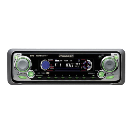
Pioneer DEH-P4500R Service Manual
Multi-cd control high power cd player with rds tuner
Hide thumbs
Also See for DEH-P4500R:
- Operation manual (88 pages) ,
- Installation manual (9 pages) ,
- Service manual (69 pages)
Table of Contents
Advertisement
Quick Links
Service
Manual
MULTI-CD CONTROL HIGH POWER CD PLAYER WITH RDS TUNER
DEH-P4500R
- This service manual should be used together with the following manual(s):
Model No.
Order No.
CX-3026
CRT2944
For details, refer to "Important symbols for good services".
PIONEER CORPORATION
PIONEER ELECTRONICS (USA) INC.
PIONEER EUROPE NV
Haven 1087 Keetberglaan 1, 9120 Melsele, Belgium
PIONEER ELECTRONICS ASIACENTRE PTE.LTD. 253 Alexandra Road, #04-01, Singapore 159936
C PIONEER CORPORATION 2002
Mech. Module Remarks
S10
CD Mech. Module:Circuit Description, Mech.Description, Disassembly
4-1, Meguro 1-Chome, Meguro-ku, Tokyo 153-8654, Japan
P.O.Box 1760, Long Beach, CA 90801-1760 U.S.A.
DEH-P4500R/XM/EW
ORDER NO.
CRT2985
XM/EW, XN/EW
K-ZZA. NOV. 2002 Printed in Japan
Advertisement
Table of Contents

Summary of Contents for Pioneer DEH-P4500R
- Page 1 PIONEER ELECTRONICS (USA) INC. P.O.Box 1760, Long Beach, CA 90801-1760 U.S.A. PIONEER EUROPE NV Haven 1087 Keetberglaan 1, 9120 Melsele, Belgium PIONEER ELECTRONICS ASIACENTRE PTE.LTD. 253 Alexandra Road, #04-01, Singapore 159936 C PIONEER CORPORATION 2002 K-ZZA. NOV. 2002 Printed in Japan...
-
Page 2: Block Diagram And Schematic Diagram
FLPILM HOME CLMP xtalen EJTIN VDSENS LCOM LOADING/ CARRIAGE LOEJ MOTOR LCOP LOEJ CONT CONT Q804 35 36 IC 301 BA5996FP DSCSNS CLMP VDSENS Q651 CLAMP 12EJ DSCSNS 3.3V REGULATOR 3R3V IC 701 Q652 NJM2391DL1-33 IC 801 DSENS TC7SET08FU DEH-P4500R/XM/EW... -
Page 3: Panel Unit
Q1910 Q807 SWDVDD SWVDD ILLUMINATION REMOTE CONTROL SENSOR IC 1901 OPT IN RS-140 Q808 DPDT DPDT KEY MATRIX KEY DATA S802 DPDT DSENS LCD DRIVER/ X1900 KEY CONTROLLER KYDT KYDT KTDT IC 1900 PD6294A 08FU Q806 BL+B CN1951 CN1950 DEH-P4500R/XM/EW... -
Page 4: Overall Connection Diagram(Guide Page)
OVERALL CONNECTION DIAGRAM(GUIDE PAGE) Note: When ordering service parts, be sure to refer to “EXPLODED VIEWS AND PARTS LIST” or “ELECTRICAL PARTS LIST”. Large size SCH diagram Guide page Detailed page EJECT SW PANEL UNIT DEH-P4500R/XM/EW... - Page 5 DSENS SW FL— RR— FR— BACK For resistors and capacitors in the circuit diagrams, their resistance values or capacitance values are expressed in codes: *Capacitors Ex. *Resistors Code Practical value Code Practical value 12k ohms 0.01uF 10k ohms 101/10 100uF/10V DEH-P4500R/XM/EW...
- Page 6 FM/AM TUNER UNIT DEH-P4500R/XM/EW...
- Page 7 KEYBOARD UNIT CN701 CD CORE UNIT (S10) A-a B DEH-P4500R/XM/EW...
- Page 8 DEH-P4500R/XM/EW...
- Page 9 DEH-P4500R/XM/EW...
-
Page 10: Keyboard Unit
3.3 KEYBOARD UNIT CL-195PG-CD CL-195PG-CD CL-195PG-CD CL-195PG-CD DEH-P4500R/XM/EW... - Page 11 KEYBOARD UNIT CL-195PG-CD PG-CD PG-CD PG-CD CL-195PG-CD CL-195PG-CD PG-CD CL-195PG-CD DEH-P4500R/XM/EW...
-
Page 12: Cd Mechanism Module
3.4 CD MECHANISM MODULE Pickup Unit(Service)(P10) MOTOR DRIVER SPINDLE MOTOR M1 CXB6007 LOADING/CARRIAGE MOTOR M2 CXB8933 3.3V REGULATOR DEH-P4500R/XM/EW... - Page 13 S901 : HOME SWITCH..ON-OFF S902 : CLAMP SWITCH..ON-OFF S903 : DSCSNS SWITCH..ON-OFF RF AMP / SERVO / DSP S904 : 12EJ SWITCH..ON-OFF S905 : 8EJ SWITCH..ON-OFF DAC / LPF The underlined indicates the switch position. CD CORE UNIT (S10) CN651 CN??? DEH-P4500R/XM/EW...
- Page 14 # RFAGC 500mV/div 200ms/div 500mV/div 2ms/div 1V/div 500µs/div ! FE # RFAGC 0 TE 500mV/div 500mV/div 500mV/div 7 TIN 500mV/div Focus Search When "Tracking Open" 1 Track Jump Ref.: Ref.: Ref.: REFO REFO REFO Mode: Mode: Mode: TEST TEST TEST DEH-P4500R/XM/EW...
- Page 15 1V/div 200µs/div 5V/div 200ms/div 5V/div 200ms/div % ROUT 2 CLCONT 2 CLCONT 1V/div 5V/div 5V/div 3 LOEJ 3 LOEJ 5V/div 5V/div Analog Audio When "Eject"(12cm CD) When "Eject"(8cm CD) Ref.: Ref.: Ref.: AGND Mode: Mode: Mode: Normal Normal Normal DEH-P4500R/XM/EW...
-
Page 16: Error Mode
Remarks: Mechanical errors are not displayed (because a CD is turned off in these errors). Unreadable TOC does not constitute an error. An intended operation continues in this case. Upper digits of an error code are subdivided as shown below: 1x: Setup relevant errors, 3x: Search relevant errors, Ax: Other errors. DEH-P4500R/XM/EW... -
Page 17: General Information
Grille Assy. Grille Assy Fig.1 Removing the Tuner Amp Unit (Fig.2) Remove the screw. Remove the three screws. Straight the tabs at three locations indicated. Remove the screw and then remove the Tuner Amp Unit. Tuner Amp Unit Fig.2 DEH-P4500R/XM/EW... - Page 18 4. While releasing from the hook of the inner holder, lift the end of the feed screw. Feed Screw Caution: In assembling, move the planet gear to the load/eject position before setting the feed screw in the inner holder. Inner Holder Planet Gear DEH-P4500R/XM/EW...
-
Page 19: Connector Function Description
7.1.2 CONNECTOR FUNCTION DESCRIPTION DEH-P4500R/XM/EW... - Page 20 22 AUDIOGND audio ground Ground of audio block 23 L ch O L channel output FM stereo “L-ch” signal output or AM audio output 24 R ch O R channel output FM stereo “R-ch” signal output or AM audio output DEH-P4500R/XM/EW...


