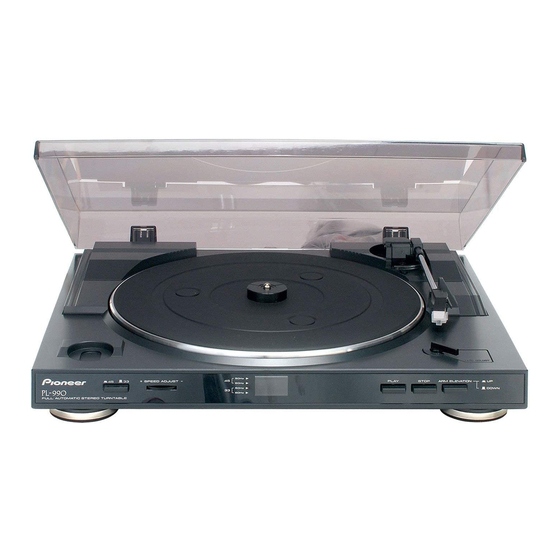
Pioneer PL-990 Manual
Hide thumbs
Also See for PL-990:
- Operating instructions manual (26 pages) ,
- Service manual (13 pages) ,
- Specifications (1 page)
Advertisement
Quick Links
Advertisement

Summary of Contents for Pioneer PL-990
- Page 1 Add A PreAmp On/Off Swith to Pioneer PL-990 (ca. 2014 Model) D. MCDONALD 14-FEBRUARY-2016...
- Page 2 BACKGROUND • Pioneer PL-990 Turntable has a built-in PreAmplifier • This is useful for many because the Turntable Output is already amplified, and it can be connected to AUX or CD (Line Level) Inputs • If a PreAmplifier is NOT present in a turntable, then the output from the turntable must be amplified before it becomes “Line Level”...
- Page 3 BACKGROUND • Why would one need or want a switch? • If you want to connect this turntable to the “Phono” input of your vintage amplifier and have it work correctly, then a switch will help… • If you don’t like the PreAmplifier included with this Turntable and want to use one of your own choosing, then a switch will help…...
- Page 4 BACKGROUND • It appears that this Turntable model was designed with the capability of having a PreAmp On/Off switch. • This option seems to have only been enabled rarely, if ever. • There is a hole molded in the plastic below the platter which allows access to the PreAmp PCB where a switch would have been/could have been installed •...
- Page 5 A LOOK AT WHERE THE SWITCH SHOULD BE • 1. Remove Top Cover • 2. Remove Pad, • 3. Look Here Rotate Platter (No Switch!)
- Page 6 A LOOK AT WHERE THE SWITCH SHOULD BE No Switch (As Received) • Look Here (No Switch!) • Look Here (No Switch!)
- Page 7 WHAT TO DO (SUMMARY) • Dismantle Turntable, to gain access to PreAmp PCB • Remove some jumpers from the PCB • Some jumpers are present which make the PCB Default to PreAmp Always-On • Install some additional jumpers to the PCB •...
- Page 8 MY MODEL IDENTIFICATION • Pioneer PL-990 • Mfr Date: Jan-2014 • Made in China...
- Page 9 DISMANTLE THE TURNTABLE...
- Page 10 REMOVE THE PLATTER • Unhook the Belt • Then Pull the Platter straight up...
- Page 11 TAKE CARE OF THE LOOSE BITS • Fix the Tone Arm • Put the Needle Guard On • Remove the 45 Adapter...
- Page 12 REMOVE THE BOTTOM PLASTIC CASE • Remove the (6) screws with arrows pointing to them • Take off the Bottom Cover...
- Page 13 LOCATE THE AMPLIFIER BOARD • There are 3 screws to remove in order to gain better access to the board. Note: This is an “After” photo, with my white wire jumper installed already.
- Page 14 ABOUT THE SWITCH CONNECTIONS...
- Page 15 Switch Contact Info (Top Row = Left Channel, Bottom Row = Right): • S1 = Unamplified, From Cartridge Input • S2 = Output to External RCA Connectors • S3 = Amplified, from PreAmp Circuit S1 S2 S3...
- Page 16 REMOVE 2 JUMPERS FROM THE PCB...
- Page 17 • Remove Jumpers JR17 and JR18 (Little Black Things with “0” are Jumpers) • These two bypass the switch location and by Default send the Amplified Signal to the Outputs...
- Page 18 ADD 2 JUMPERS TO THE PCB...
- Page 19 Add Jumpers for L/R Unamplified Inputs • Jumper these two pairs of points, so the unamplified input signal can reach the switch location...
- Page 20 Add Jumpers for L/R Unamplified Inputs • Jumpers Installed J2 – Jumper Installed J2 – No Jumper (As Received) J1 – Jumper Installed. Long wire used because no shorter connection points are available...
- Page 21 INSTALL AN APPROPRIATE SWITCH...
- Page 22 • Switch Installed • I was able to find this switch in my “junk pile,” and it fit very well. No Switch (As Received) Switch Installed...
- Page 23 REASSEMBLE THE TURNTABLE...
- Page 24 REASSEMBLE THE TURNTABLE • Don’t forget to hook up the Belt when you put the Platter back on • Now you can connect this turntable to… • Internal Amp “ON” AUX/CD input • Internal Amp “OFF” Phono input Switch Installed!


