Table of Contents
Advertisement
Quick Links
Advertisement
Table of Contents

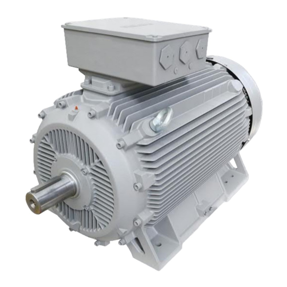
Summary of Contents for Siemens SIMOTICS SD 1LE8 Series
- Page 1 Installation and Maintenance Manual 2019.03...
- Page 3 ......................................2 ..................................2 ..................................2 ..............................2 ..................................3 ......................................4 ....................................4 ..................................4 ..............................5 ..................................5 ..............................7 ..................................8 .................................8 ......................................9 ..................................9 ................................9 ....................9 ..................................10 ................................10 ..................................11 ....................
- Page 4 SIMOTICS SD 1LE8 IEC60034-5 IP55 • 1000 m -20 ºC ~ +40 ºC • • ºC ºC 100 % ºC ºC <T 30 95 % ºC ºC <T 40 55 % GB18613-2012 IC411 IEC/EN 60034-6 SIMOTICS SD 1LE8 IC416 IEC/EN 60034...
- Page 6 3.1.1 DIN4024 (FS) 0.10 0.15 0.20 3.1.2 >0.05mm 3.1.3 3.1.4 4×90º...
- Page 7 ±5% ±2% ±10%...
- Page 8 W2 U2 U1 V1 W1 U2 (V2, W2) U1(W2) V1(U2) W1(V2) • PTC — 145 ºC 155 ºC • PT100 — • KTY84-130 —...
- Page 9 PT100 KTY84-130 PT100 PTC PT100 KTY84-130 1HE1-1HE2 2HE1-2HE2 690V =0.69kV×0.5M /kV=0.345 500V 25 ºC±15 ºC 2PTC PT100 2PT100 KTY84...
- Page 10 2PTC PT100 2PT100 500V PT100 IGBT IEC 60034-1...
- Page 11 “5 ” DIN VDE 0105 • • • • • 40,000 20,000 20,000 40,000 40 ºC 40 ºC 10 ºC UNIREX N3 Esso DIN 51825-K3N...
- Page 12 — ±10%...
-
Page 15: Table Of Contents
Content 1.0 INTRODUCTION ....................14 1.1 Application Scope ..................14 1.2 Cooling method ..................... 14 1.3 Types of construction/method of installation ..........14 2.0 HANDLING AND STORAGE ................15 3.0 COMMISSIONING................... 16 3.1 Installation....................16 3.2 Terminal Box ..................... 17 3.3 Balancing and Transmission Coupling ............ -
Page 17: Handling And Storage
Note: 1) At outdoor application, the using of protective cover (option code H00) is recommended; 2) At out door application the protection of shaft again jet-water is recommended; 2.0 HANDLING AND STORAGE When lifting the motors, always use the lifting eyes provided or machines may only be hoisted in a position corresponding to their basic type of construction. -
Page 18: Commissioning
The service life of the motor can be considerably reduced if the storage period extends beyond 2 years in environments with high moisture and dirt. If necessary, the insulation resistance of the winding could be measured determine the health of the motor prior to installation and start-up, (see Section 3.5. -
Page 19: Terminal Box
3.1.2 Installation requirement Because of the manufacture tolerance and cumulate errors existing in mechanical parts, clearance may exist between the motor feet plane and the foundation support surface. When install motors, the clearance size must be measured carefully by feeler gauge. For clearance which >0.05mm, shim with proper thickness should be inserted. -
Page 20: Electrical Connection
3.4 Electrical connection All work must be carried out by skilled worker. Before starting any work, be sure to isolate the machine from the main and auxiliary power supply as applicable. Mains must be secured against accidental switch on. There are six power supply terminals and two earthing positions located in the terminal box. There is an earthing point located on the base of the frame. - Page 21 Star connection A star connection is obtained by connecting W2, U2, V2 terminals to each other and the U1, V1, W1 terminals to the mains. U2 (V2, W2) Delta connection A delta connection is obtained by connecting the end of a phase to the beginning of the next phase.
-
Page 23: Insulation Resistance Inspection
Insulation resistance The minimum insulation resistance between new, cleaned or repaired windings with reference to ground is 10 M . The critical insulation resistance (Recruit) is calculated by multiplying the rated voltage, e.g. 0.69 kV AC, with the constant factor (0.5M / kV): Recruit = 0.69 kV×0.5 M /kV = 0.345 M Measurement... -
Page 24: Maintenance
Electromagnetic compatibility In application where the motor is driven by a drive, the degree of electrical interference depends on the type of used drive (type, number of IGBTs, interference suppression measures, and manufacturer), cabling, distance and application requirements. The installation guidelines of the drive manufacturer with regards to electromagnetic compatibility must be considered at all times during the design and implementation phases. -
Page 26: Bearing Replacement
It is recommended that the DE and NDE bearings should be re-greased while the motor is in operating and at operating temperature. If it is not possible to re-grease the motor during operation, then it recommended that a partial amount of the grease is injected and then the motor energized and rotated for a few revolutions to allow for grease dispersion. -
Page 27: Drain Plug
4.6 Condensation drain plug Based on the motor's construction and mounting type, please consider to select the drainage hole option (option code H03). Drainage hole is on motor's frame, and it is closed by a plastic plug when delivered. 5.0 START UP Preliminary Inspection Before applying power to the motor for the first time, it is recommended to check: 1) All retaining bolts are tightened including transmission coupling and alignment... - Page 29 www.ad.siemens.com.cn...


