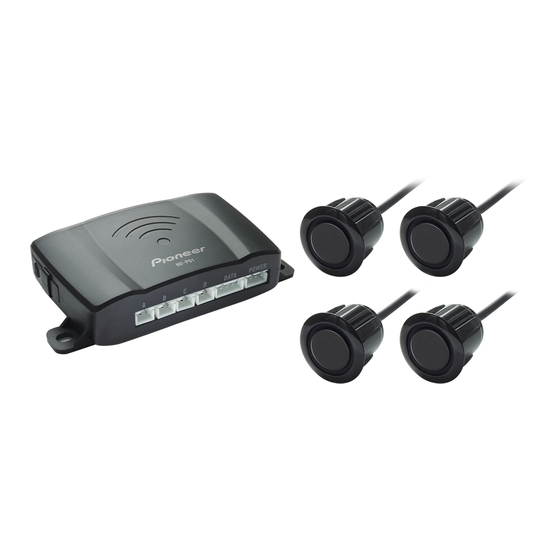
Pioneer ND-PS1 Manual
Parking sensor
Hide thumbs
Also See for ND-PS1:
- Instruction manual (112 pages) ,
- Installation manual (36 pages) ,
- Instructions manual (18 pages)
Table of Contents
Advertisement
Quick Links
Advertisement
Table of Contents

Summary of Contents for Pioneer ND-PS1
- Page 1 ND-PS1 Manual Parking Sensor...
- Page 2 Warning • Consult your dealer if installation requires drilling of holes or other modifications to the vehicle. • Do not attempt to install or service this product by yourself. Installation or servicing of this product by persons without training and experience in electronic equipment and automotive accessories may be dangerous and could expose you to the risk of electric shock, injury, or other hazards. • This product is a reversing aid and Pioneer accepts no responsibility for any loss or damage of any kind incurred as a result of the use of the sensors.
-
Page 3: Safety Standard
SAFETY STANDARD CAUTION This product is evaluated in moderate and tropical climate condition under the Audio, video and similar electronic apparatus - Safety requirements, IEC 60065. The graphical symbol placed on the product means direct current. - Page 4 NOTES • The car must be powered off during the installation of the device. • The sensors may be affected in the following situations: heavy rain, gravel road, bumpy road, sloping road, grassy road, very cold or hot weather, moist weather, the sensors are covered by snow or ice, etc. • The sensors should be installed appropriately. • Do not install the sensors on a metallic bumper. • Avoid installing the control box in or near vent pipe or wiring. • Make sure that the device works properly before and after installing this product. <Test Method: Refer to TEST BEFORE INSTALLATION>...
- Page 5 LIMITATIONS Fig 1 Fig 2 Fig 1: The display may not be the same as the real condition due to the sensor position, obstacle, shape, reflection condition, and so on. If an object is too high If there is a very small object When backing up downhill Fig 2: Objects hard to be detected in the following conditions. Smooth slope Smooth round objects Objects that absorb waves (e.g. cotton)
-
Page 6: General Installation Diagram
GENERAL INSTALLATION DIAGRAM Control box Power cable Sensor Connection cable Pioneer compatible unit Hole saw (sold separately) -
Page 7: Wiring Diagram
WIRING DIAGRAM Reversing light (Red) Ground (Black) To the compatible unit... - Page 8 TEST BEFORE INSTALLATION 2.5 m Test the distance with a hard plate of 100 cm × 100 cm or a wall. The farthest detection distance is 2.5m. (The shortest detection distance is 30 cm). Make sure to check the operation before the installation.
-
Page 9: Sensor Installation
SENSOR INSTALLATION Fig 1 55 cm 65 cm Fig 2 40 cm 40 cm 20 cm 20 cm Fig 1: Preset of sensor installation height is 55-65 cm vertically to the ground. Fig 2: Apply the adhesive paper to the appropriate height position of the sensor, and then measure the installation position of the 4 sensors and mark with a pen. - Page 10 SENSOR INSTALLATION2 19 mm Fig 1 Fig 2 Fig 1: Install the 19 mm hole saw (supplied) into the electric drill and drill the holes in the marked 4 positions. Fig 2: Insert the sensors into the holes one by one and tighten them. Caution Never paint on the sensors. It is quite difficult to receive ultrasonic waves. NOTES • Make sure the arrow direction points upward when inserting the sensor into the hole. • Make sure to install the sensors snugly.
-
Page 11: Control Box Installation
CONTROL BOX INSTALLATION The red wire is connected to the positive of the reversing light and the black wire is connected to the ground. Use the insulation tape to cover the joint which is connected by soldering iron. Ground (Black) Reversing light (Red) - Page 12 CONTROL BOX INSTALLATION...
-
Page 13: Specification
SPECIFICATION Control box specification Nominal voltage : 14.4 V DC Operating voltage : 10.8~15.1 V DC Rated current : 10~30 mA at 14.4 V DC Detection range : 0.3 m~2.5 m Operation temperature range : -20 ˚C~70 ˚C Dimensions (WxHxD) : 105.3 mm × 21.8 mm × 56.0 mm Weight : 52 g Cable length Power cable : 1 m Connection cable : 5 m Sensor Specifications Center frequency : 40 kHz Directivity X-axis : 70° Directivity Y-axis : 70° Maximun input voltage : 120 Vp-p (at 40 kHz) IP code : IP67 Operation temperature range : -30 ˚C~80 ˚C Dimensions : φ23.5 mm × 19.8 mm (Exclude cable) Weight : 50 g/1 pc Cable length : 2.5 m Learn more about cameras and driver safety we have.


