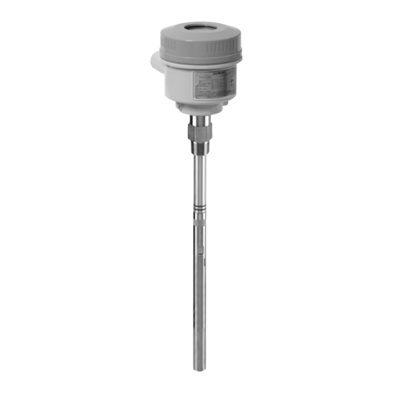
Siemens Pointek CLS200 Application Examples
Hide thumbs
Also See for Pointek CLS200:
- Quick start manual (200 pages) ,
- Operating instructions manual (150 pages) ,
- Instruction manual (114 pages)
Summary of Contents for Siemens Pointek CLS200
- Page 1 Introduction Overview Planning/configuring Pointek CLS200 Capacitance Switch (Standard Version) Application examples 09/2020 AG080910...
- Page 2 Note the following: WARNING Siemens products may only be used for the applications described in the catalog and in the relevant technical documentation. If products and components from other manufacturers are used, these must be recommended or approved by Siemens. Proper transport, storage, installation, assembly, commissioning, operation and maintenance are required to ensure that the products operate safely and without any problems.
-
Page 3: Table Of Contents
Calibration for demanding applications (Failsafe low, no delay) ..........7 Calibration for interface detection (Failsafe low, no delay) ............ 7 Alarm Delay Function ......................8 Testing the Alarm Delay ....................... 8 Operation ..........................8 Pointek CLS200 Capacitance Switch (Standard Version) Application examples, 09/2020, AG080910... -
Page 4: Introduction
Objective The objective of this application guide is to help the user become familiar with the steps required to set up and calibrate the Pointek CLS200 (Standard Version). This application guide applies to any models manufactured after August 1, 2010. -
Page 5: Overview
PBD/A8xxxxxx or higher. (For example, PBD/A9xxxxxx or PBD/B2xxxxxx.) Included in the guide are the appropriate start up procedures to quickly and effectively set up the Pointek CLS200 (Standard Version) capacitance switch for general applications, demanding applications and interface detection. It also contains instructions for adjusting the setpoint and alarm delay. -
Page 6: Planning/Configuring
Specifications and Troubleshooting sections of the operating instructions. Pointek CLS200 Applications Pointek CLS200 can be set up for three different applications which are described in the table below. Use the calibration procedure for the application that most closely describes your operation. -
Page 7: Calibration For General Applications (Failsafe Low, No Delay)
6. If the yellow sensor status LED (L1) is on, proceed to step 7. If L1 is off, turn the trip point potentiometer (P2) counter-clockwise until it just turns on. Pointek CLS200 Capacitance Switch (Standard Version) Application examples, 09/2020, AG080910... -
Page 8: Alarm Delay Function
8. Enable RUN mode by setting DIP switch S5 to OFF (rocker down). Alarm Delay Function If you want to slow the Pointek CLS200 response, to compensate for turbulence or false readings, set a delay interval using the delay potentiometer (P1) and set DIP switches S1 and/or S2 to the OFF position to enable the delay for either alarm activation (S1 OFF), alarm de-activation (S2 OFF), or both (S1 and S2 OFF).


