Advertisement
Quick Links
Getting Started Guide & Warranty
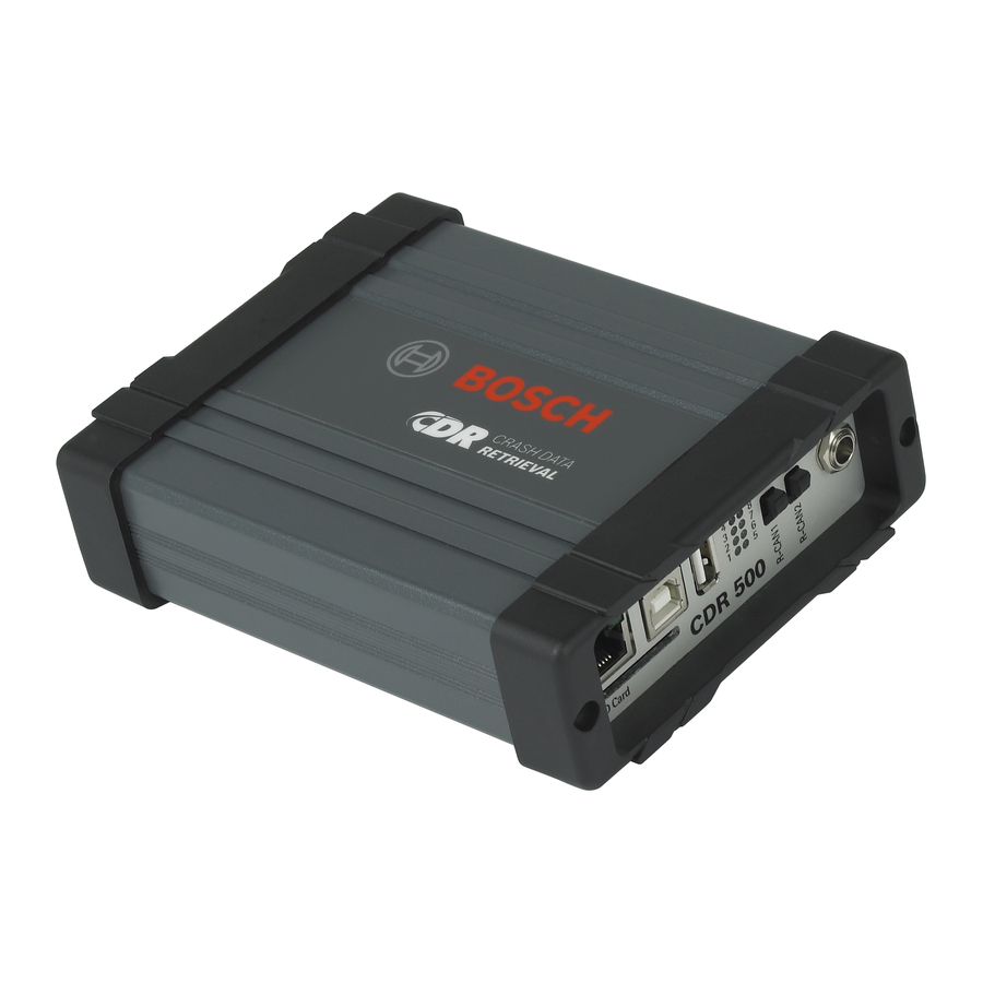
CDR 500 Kit
Thank you for purchasing the CDR 500 Kit. The CDR 500
Adapter enables the CDR Tool to retrieve EDR data directly
from ECUs with a FlexRay communications network. This
advanced technology is much different than traditional
CAN or K-Line networks currently supported by the CDR
Tool.
The first application of the CDR 500 will be for select
BMW and MINI vehicles. In the near future, the CDR 500
will be required for direct-to-module EDR downloads on
Audi and other vehicles.
Kit Contents:
Qty
Description
(1)
CDR 500 Adapter
(1)
Interface Cable
(1)
6' USB Cable
Refer to the CDR Tool software help file for vehicle
application, connection instructions and using the CDR
500 for the first time.
System Requirements:
` PC computer system requirements are the same as
those specified for the CDR Tool software
` Two USB ports with mass storage device support
enabled (e.g., USB Flash Drive)
Getting Started Guide & Warranty (P/N: 1699200145, rev A)
CDR 500 Adapter:
The CDR 500 can only be used in conjunction with the
CDR Interface Module and the F00K108387 ACM Power
Adapter. Power to the CDR 500 is supplied through the
ACM Adapter and controlled by the CDR Tool software.
Inputs/Outputs:
ATTENTION:
When operating the CDR 500, use
supply provided with the CDR Tool Kit when powering
the device directly or through the ACM Power Adapter. Do
not use another power source including a vehicle battery.
P/N
Failure to do so may cause damage to the adapter and void
F00K108803
the warranty.
1699200106
06501262
Interface Cable:
The CDR 500 interface cable is used to connect the
F00K108387 ACM Power Adapter to the X1 port of the CDR
500. This cable carries the necessary signals between the
CDR Interface Module and the CDR 500 Adapter.
6' USB Cable:
Use this cable to connect your PC to the CDR 500 Adapter for
future updates. The CDR Tool software will guide you through
the update process when updates become available.
– LAN - not used
– SD Card - not used
–
USB-B - device reprogramming
– USB-A - not used
–
LEDs 1-8 - activity indicator lights
– R-CAN1 switch - any position
– R-CAN2 switch - any position
–
6-36V DC - power jack, use only
as instructed in the CDR Tool
help file
–
X2 - ACM direct to module cable
connection
–
X1 - CDR 500 interface cable
connection
–
only the AC power
© Copyright 2014 Bosch Automotive Service Solutions
Advertisement

Summary of Contents for Bosch CDR 500 Kit
- Page 1 – USB-A - not used – LEDs 1-8 - activity indicator lights Thank you for purchasing the CDR 500 Kit. The CDR 500 – R-CAN1 switch - any position – R-CAN2 switch - any position Adapter enables the CDR Tool to retrieve EDR data directly –...
- Page 2 Bosch CDR 500 Adapter Warranty: Connecting the CDR 500: Bosch offers a limited, 24 month warranty on all CDR hardware. The CDR Tool software and help file will guide you through For details on the warranty, refer to the CDR Tool Operator’s connecting, updating and using your new CDR 500 Adapter.


