Advertisement
Quick Links
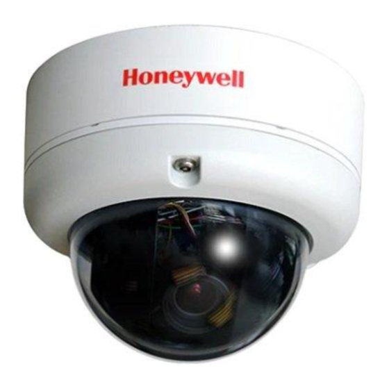
HD3UH(X) Ultra WDR Indoor Minidome Camera Quick Installation Guide
This document describes how to install the HD3UH(X) minidome camera.
The camera can be installed to a wall or ceiling using one of the following methods:
•
surface mount
•
flush (in-ceiling) mount
•
pendant mount
Important Safety Instructions
•
Read and keep these instructions.
•
Please ensure that your installation area can safely support the weight of the camera.
•
Do not install the camera in extreme temperature conditions. Only use the camera where
temperatures are within the limits shown in the specifications section of the user guide.
Be especially careful to provide ventilation when operating under high temperatures.
•
Do not aim the camera towards an extreme light source to prevent damaging the CCD.
•
This camera is rated for indoor operation; do not expose this camera to rain or moisture.
•
Do not touch the camera lens, dome or bezel (front glass plate).
•
Do not drop the camera or subject it to physical shock.
•
Do not use a strong or abrasive detergent when cleaning the camera.
WARNING
Installation and servicing should be performed only
by qualified and experienced technicians to conform to all local
codes and to maintain your warranty.
WARNING
This device is configured for 12 V DC or 24 V AC
operation. Do not connect to a higher voltage. Use only with NRTL-
approved Class 2 power supplies.
RISK OF ELECTRIC SHOCK
DO NOT OPEN
CAUTION:
TO REDUCE THE RISK OF ELECTRIC SHOCK,
DO NOT REMOVE COVER (OR BACK).
NO USER SERVICEABLE PARTS INSIDE.
REFER SERVICING TO QUALIFIED SERVICE PERSONNEL.
Package Contents
Before you begin, check that you have the following items:
• HD3UH(X) minidome camera
• 2nd video cable
• DC power jack flying lead
Camera Overview
Power Cable
24 V AC
Base Skirt
Gimbal Base
Camera Control Board
Power Board
Gimbal
Lens
• Hardware kit consisting of four (4)
mounting screws and anchors
• Mounting template
Video Cable
Mounting Screws
Main Camera Assembly
Dome Cover
1
Installing the Camera
Disassembling the Camera
1.
Insert a coin into the notch on the camera base
and twist. Set the dome cover aside.
2.
Grasp the gimbal base with one hand and the base
skirt with the other and twist the gimbal base
clockwise to remove it from the skirt.
Locked
Unlocked
3.
Remove the main camera assembly from the base skirt.
Connecting the Cables
Connect the power and video cables.
24 V AC
Mounting the Camera
Surface Mount
1.
Pre-drill the mounting holes using the
supplied mounting template as a guide.
2.
Attach the base skirt to the mounting surface
using the supplied mounting screws and
anchors.
Note
For added support, you can attach the base
skirt to a 2S junction box.
3.
Re-attach the main camera assembly to the
base skirt. Twist the gimbal base counterclockwise to lock it in place.
4.
Adjust the gimbal position, field of view, and focus as desired
(see
Setting Up the
Camera).
Flush Mount
1.
Cut a hole in the mounting surface using the supplied mounting template as a guide.
2.
Insert the main camera assembly through the hole.
CCTV Monitor
Unlocked
Locked
Document 800-20476V1 – Rev A – 05/2015
1
Advertisement

Summary of Contents for Honeywell HD3UH
- Page 1 HD3UH(X) Ultra WDR Indoor Minidome Camera Quick Installation Guide Installing the Camera This document describes how to install the HD3UH(X) minidome camera. The camera can be installed to a wall or ceiling using one of the following methods: • surface mount Disassembling the Camera •...
- Page 2 2nd Video Out Document 800-20476V1 – Rev A – 05/2015 © 2015 Honeywell International Inc. All rights reserved. No part of this publication may be reproduced by Spot Monitor any means without written permission from Honeywell. The information in this publication is believed to be accurate in all respects.


