Advertisement
Quick Links
GENERAL
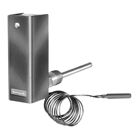
L8100A,B, and C are immersion type controllers for
regulating and limiting the tank temperature in water heaters.
As the water temperature rises past the setpoint, the
controller switches off the gas valve.
® U.S. Registered Trademark
Copyright © 1995 Honeywell Inc. • All Rights Reserved
L8100A,B,C Aquastat
®
FEATURES
• L8100A regulates tank temperature and provides
energy cutoff (ECO) action on a temperature rise past
the setpoint.
• L8100B regulates temperature and provides ECO
action on a temperature rise past the setpoint. This
model includes a second sensing element that senses
average water temperature to minimize stacking.
• L8100C includes a second sensing element that
senses average water temperature to minimize
stacking, but does not include ECO action.
• Fluid filled element operates single pole single throw
(spst) snap-acting Micro Switch™.
• Energy cutoff (ECO) switch enclosed in factory
installed well of L8100A,B interrupts the thermocouple
circuit or main valve before the tank reaches
maximum temperature of 210°F (99°C).
• Internal adjustment screw.
• Immersion well is factory installed to the controller.
• Special switch terminal provides three-wire hookup
from Aquastat® controller to gas valve.
• Four terminal models for manual reset with S86/
VR8204/VR8440.
General ............................................................................... 1
Features .............................................................................. 1
Specifications ...................................................................... 2
Ordering Information ........................................................... 2
Installation ........................................................................... 3
Operation and Checkout ..................................................... 8
Controllers
PRODUCT DATA
Contents
60-2336-3
Advertisement

Summary of Contents for Honeywell Aquastat L8100C
-
Page 1: Table Of Contents
• Four terminal models for manual reset with S86/ VR8204/VR8440. Contents General ................1 Features ................1 Specifications ..............2 Ordering Information ............2 Installation ................3 Operation and Checkout ............. 8 ® U.S. Registered Trademark 60-2336-3 Copyright © 1995 Honeywell Inc. • All Rights Reserved... -
Page 2: Specifications
If you have additional questions, need further information, or would like to comment on our products or services, please write or phone: 1. Your local Honeywell Home and Building Control Sales Office (check white pages of your phone directory). 2. Home and Building Control Customer Relations... -
Page 3: Installation
L8100A,B,C Aquastat CONTROLLERS ® Available Options: INSTALLATION External adjustment screw and visible control point scale. When Installing this Product... Factory set stop at 140°F (60°C). Read instructions carefully. Failure to follow them could Approvals: damage the product or cause a hazardous condition. Underwriters Laboratories Inc. - Page 4 L8100A,B,C Aquastat CONTROLLERS ® IMPORTANT The controller immersion well is factory-installed to the controller. Do not remove the immersion well, this could damage the ECO switch. JAWS If system is filled, drain to a point below the tapping. SPREAD JAWS Remove plug from tapping.
- Page 5 L8100A,B,C Aquastat CONTROLLERS ® L8100A,B L8100A,B CONTROLLER CONTROLLER ECO SWITCH ECO SWITCH POWERPILE® POWERPILE® MILLIVOLT VS820 MILLIVOLT VS890 GENERATOR GENERATOR GAS VALVE VALVE OPERATOR VALVE OPERATOR COIL COIL PILOTSTAT® POWER UNIT COIL PILOTSTAT® POWER USE 4-TERMINAL VS820 GAS VALVE. UNIT COIL DOTTED LINE SHOWS INTERNAL WIRING.
- Page 6 L8100A,B,C Aquastat CONTROLLERS ® L8100C L8100A,B (HOT) CONTROLLER ECO SWITCH V800 POWERPILE® MILLIVOLT VS890 GENERATOR VALVE OPERATOR COIL VALVE OPERATOR COIL PILOTSTAT® POWER UNIT COIL POWER SUPPLY. PROVIDE DISCONNECT MEANS AND DOTTED LINE SHOWS INTERNAL WIRING. OVERLOAD PROTECTION AS REQUIRED. INSTALL FIELD JUMPER BETWEEN TERMINALS TH AND PP.
- Page 7 L8100A,B,C Aquastat CONTROLLERS ® L8100A,B CONTROLLER S86E,F,G,H ECO SWITCH (HOT) TO GAS MV/PV VALVE TH-R TH-W POWER SUPPLY. PROVIDE DISCONNECT MEANS AND OVERLOAD PROTECTION AS REQUIRED. S86E AND F MODELS ARE AVAILABLE WITH OR WITHOUT TH-R AND TH-W TERMINALS. SELECTED MODELS HAVE 3/16 AND 1/4 IN. TAB TERMINALS. M4756 Fig.
-
Page 8: Operation And Checkout
L8100A,B,C Aquastat CONTROLLERS ® L8100A,B CONTROLLER S86H ECO SWITCH MV/PV TH-R (HOT) TH-W VR8440 VALVE TERMINALS TH-TR POWER SUPPLY. PROVIDE DISCONNECT MEANS AND OVERLOAD PROTECTION AS REQUIRED. FACTORY-INSTALLED WIRES, DO NOT REMOVE. SELECTED MODELS HAVE 3/16 AND 1/4 IN. TAB TERMINALS. M4757 Fig. - Page 9 L8100A,B,C Aquastat CONTROLLERS ® Checkout Check to verify the Aquastat® controller was installed and adjusted properly. Put the system into operation and observe the action of the device through several cycles to make certain that it provides proper control of the system. Further adjustments can then be made to meet more exact comfort requirements.
- Page 10 L8100A,B,C Aquastat CONTROLLERS ® 60-2336—3...
- Page 11 L8100A,B,C Aquastat CONTROLLERS ® 60-2336—3...
- Page 12 L8100A,B,C Aquastat CONTROLLERS ® Home and Building Control Home and Building Control Helping You Control Your World Honeywell Inc. Honeywell Limited-Honeywell Limitée 1985 Douglas Drive North 740 Ellesmere Road Golden Valley, MN 55422 Scarborough, Ontario QUALITY IS KEY M1P 2V9 60-2336—3...


