Advertisement
Quick Links
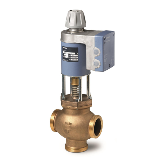
MXG461B Series
Modulating Control Valves with
Magnetic Actuators, Positioning
Control and Position Feedback for
Domestic Water
Description
Features
Product Numbers
Warning/Caution
Notations
Control valves with magnetic actuators, for modulating control of domestic water, cold
water and hot water systems.
•
Fast positioning time (< 2 seconds)
•
Selectable valve characteristic: Equal percentage or linear
•
Selectable standard interface: 0/2 to 10 Vdc or 0/4 to 20 mA
•
High resolution (>1:1000)
•
High rangeability
•
Wear-free inductive stroke measurement
•
Spring return A → AB closed when de-energized
•
Positioning control and position feedback signal
•
Low-friction, heavy-duty and maintenance-free
•
Accepts 0 to 20 Vdc phase-cut control signal input
See Table 1.
WARNING:
CAUTION:
Technical Instructions
Document No. 125-4461
Personal injury or loss of life may occur if you do not
follow the procedures as specified.
Equipment damage or loss of data may occur if you
do not follow the procedures as specified.
October 23, 2018
Siemens Industry, Inc.
Advertisement

Summary of Contents for Siemens MXG461B Series
- Page 1 Technical Instructions Document No. 125-4461 October 23, 2018 MXG461B Series Modulating Control Valves with Magnetic Actuators, Positioning Control and Position Feedback for Domestic Water Description Control valves with magnetic actuators, for modulating control of domestic water, cold water and hot water systems.
- Page 2 Technical Instructions MXG461B Series Modulating Control Valve Document Number 125-4461 with Magnetic Actuator October 23, 2018 Application The MX4G61B Series valves are through-port or mixing valves with magnetic actuators. The actuator is equipped with an electronics module for positioning control and position feedback.
- Page 3 MXG461B Series Modulating Control Valve Technical Instructions with Magnetic Actuator Document Number 125-4461 October 23, 2018 Control The magnetic actuator can be driven by any controller with a 0/2 to 10 Vdc or 0/4 to 20 mA output signal. To achieve optimum control performance, it is recommended to use a 4-wire connection for the valve.
- Page 4 Technical Instructions MXG461B Series Modulating Control Valve Document Number 125-4461 with Magnetic Actuator October 23, 2018 Manual Adjustment Press (a) and turn the hand wheel (b): • clockwise (CW). Control path A → AB can be mechanically opened to between 80% and 90%, •...
- Page 5 MXG461B Series Modulating Control Valve Technical Instructions with Magnetic Actuator Document Number 125-4461 October 23, 2018 DIP Switches, Continued Figure 4. Assignment of Positioning Figure 5. Selection of Valve Signal Y: Voltage or Current. Characteristic: Equal-Percentage or Linear. Output signal U (position feedback signal) is dependent on the load resistance.
-
Page 6: Installation Notes
Technical Instructions MXG461B Series Modulating Control Valve Document Number 125-4461 with Magnetic Actuator October 23, 2018 Valve Sizing Characteristic Figure 8. Equal Percentage. Figure 9. Linear. • Installation Notes Installation instructions for the valve and terminal housing are enclosed with the valve. - Page 7 MXG461B Series Modulating Control Valve Technical Instructions with Magnetic Actuator Document Number 125-4461 October 23, 2018 Low-voltage use only Class 2 (SELV, PELV) Specification s 24 Vac Electrical Operating voltage 24 Vac ± 20% Frequency 45 to 65 Hz Typical power consumption...
-
Page 8: Connection Terminals
Technical Instructions MXG461B Series Modulating Control Valve Document Number 125-4461 with Magnetic Actuator October 23, 2018 Specifications, Continued Pipe connections Screwed fittings Bronze/brass Electrical connections Cable entries 2 × Ø 20.5 mm (for M20) Connection terminals Screw terminals for up to 12 AWG wires Min. -
Page 9: Application Examples
MXG461B Series Modulating Control Valve Technical Instructions with Magnetic Actuator Document Number 125-4461 October 23, 2018 Connection Terminals, Continued Controllers with phase-cut 0 to 20 Vdc Figure 13. Application This example shows only a schematic diagram, without installation-specific details. Examples CAUTION: 1. - Page 10 Technical Instructions MXG461B Series Modulating Control Valve Document Number 125-4461 with Magnetic Actuator October 23, 2018 Dimensions Figure 15. Dimensions in Inches (Millimeters). NOTE: The screwed fittings and gaskets are supplied with these valves. Product Number (in) (mm) (in) (kg) MXG461B15-0.6...


