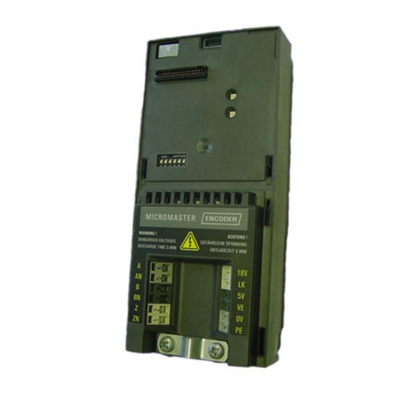
Siemens Micromaster Operating Instructions Manual
Encoder module
Hide thumbs
Also See for Micromaster:
- Operating instructions manual (42 pages) ,
- Reference manual (78 pages)
Table of Contents
Advertisement
Quick Links
Advertisement
Table of Contents

Summary of Contents for Siemens Micromaster
- Page 1 MICROMASTER Encoder Module Operating Instructions Issue 04/04 User Documentation...
-
Page 2: Foreword
Indicates that an undesirable effect or state can occur if attention is not paid to the advice given. NOTE For the purpose of this document, “Note” indicates important information relating to the product or highlights part of the documentation for special attention. MICROMASTER Encoder Module Operating Instructions A5E00146708A2... - Page 3 The user should be fully conversant with all warnings, cautions and notices contained within the MICROMASTER 440 Operating Instructions. The successful and safe operation of this equipment is dependent upon its proper handling, storage, installation, operation and maintenance.
-
Page 4: Table Of Contents
Examples of Connections ........9 Commissioning............12 TTL Encoder............13 HTL Encoder ............13 External Power Supply ..........14 Encoder Module Parameterization......15 Troubleshooting ............ 18 LED Indicators ............18 Fault Codes ............. 19 Technical Specifications ........20 MICROMASTER Encoder Module Operating Instructions A5E00146708A2... -
Page 5: Overview
The Encoder Module can use High-voltage Transistor Logic (HTL) and Transistor Transistor Logic (TTL) digital encoders. When the Encoder Module is fitted to the MICROMASTER 440 it allows closed-loop encoder feedback with the following benefits in comparison to Sensorless Vector Control (SLVC) and Variable Frequency (V/f) operation... -
Page 6: Installation
3.1.1 Preparation of the Inverter Caution The Encoder Module will only function with the MICROMASTER 440 inverters and must have Version 2.0 or above software installed. The version level of software install in the inverter can be confirmed by using one of the following procedures: By accessing parameter r0018 which displays the current software version number. - Page 7 PE terminal of the Encoder Module. Signals cables must not be installed close to power cables. Figure 3-3 Screen Clamp and PE Terminal Connections The MICROMASTER Encoder Module has 12 terminal connections, which are described in Table 3-1 below. Table 3-1 Encoder Module Terminals Terminal...
- Page 8 Installation Issue 04/04 Encoder Status LED’s The MICROMASTER Encoder Module has three LED’s, which indicate current operating status of the encoder module (see Figure 3-4 below). Figure 3-4 Encoder Module LED’s The LED’s have been designed to indicate a healthy or fault condition in...
-
Page 9: Examples Of Connections
1xP8001 Encoder blindaje U a1 U a1 U aS U a2 U a0 U a0 U a2 Designations schermo skärm +24 V MM4 Encoder Module Connections +5 V Figure 3-6 Typical Encoder Connections MICROMASTER Encoder Module Operating Instructions A5E00146708A2... - Page 10 Installation Issue 04/04 Figure 3-7 TTL Encoder Connections (5V DC) Figure 3-8 HTL Encoder Connections (18V DC) MICROMASTER Encoder Module Operating Instructions A5E00146708A2...
- Page 11 Issue 04/04 Installation Figure 3-9 Encoder with External Power Supply MICROMASTER Encoder Module Operating Instructions A5E00146708A2...
-
Page 12: Commissioning
National safety regulations are also applicable. The actions required to commission the MICROMASTER Encoder Module depend upon the type of encoder that is connected to the Encoder Module. These instructions will deal with each type of encoder individually. -
Page 13: Ttl Encoder
Encoder Module. See Figure 3-6 on page 9 and Figure 3-8 on page 11. Connect the Channel A inverted wire from the encoder to the ‘AN’ terminal on the Encoder Module. MICROMASTER Encoder Module Operating Instructions A5E00146708A2... -
Page 14: External Power Supply
24 Volts DC. The Encoder Module should be configured for the appropriate encoder type, either TTL or HTL and the power connections configured as shown in the Figures on pages 9, 10 and 11. MICROMASTER Encoder Module Operating Instructions A5E00146708A2... -
Page 15: Encoder Module Parameterization
Signal o.k. Bit03 Encoder low speed loss Bit04 HW timer used Details: See description of seven-segment display given in the "Introduction to MICROMASTER System Parameters". P0408[3] Encoder pulses per Specifies the number of encoder pulses per revolution revolution. P0491[3] Reaction on speed Selects reaction on loss of speed signal. - Page 16 P0492 > 0). If low speed encoder loss detection is disabled and encoder should be lost at low speed, then operation of motor may become unstable. P1300 Control Mode 21 = Closed loop speed control 23 = Closed loop torque control MICROMASTER Encoder Module Operating Instructions A5E00146708A2...
- Page 17 Issue 04/04 Commissioning WARNING The “Flying Start” function of the MICROMASTER 440 inverter should only be used with a Quadrature Encoder. To perform a “Flying Start” the direction of the motor must be known to the encoder attached to the motor. A Single-Channel encoder cannot determine the direction of rotation of the motor;...
-
Page 18: Troubleshooting
Troubleshooting Issue 04/04 5 Troubleshooting There are two types of fault indication on the MICROMASTER Encoder Module: Three status LED’s on the front panel for indicating the operational status of Channels A, B and Z (See Figure 5-1 below). Fault code display specific to the Encoder Module on the AOP, BOP. -
Page 19: Fault Codes
Check for correct magnitude and direction of speed. Increase the encoder loss threshold in P0492. Increase encoder low speed loss detection delay in P0494. MICROMASTER Encoder Module Operating Instructions A5E00146708A2... -
Page 20: Technical Specifications
Via Link Wire Degree of Protection IP20 Encoder Power Supply 5 V (±5%) @ 330 mA 18 V Unregulated @ 140mA short circuit proof Dimensions 164 mm (h) x 73 mm (w) x 42 mm (d) MICROMASTER Encoder Module Operating Instructions A5E00146708A2... - Page 22 Drawing Number: *A5E00146708A2* Siemens AG Bereich Automation and Drives (A&D) Geschäftsgebiet Standard Drives (SD) Postfach 3269, D-91050 Erlangen © Siemens AG, 2003 Bundesrepublik Deutschland Änderungen vorbehalten Siemens Aktiengesellschaft Drawing Number: A5E00146708A Datum: 02/02...


