Table of Contents
Advertisement
MR34 Installation Guide
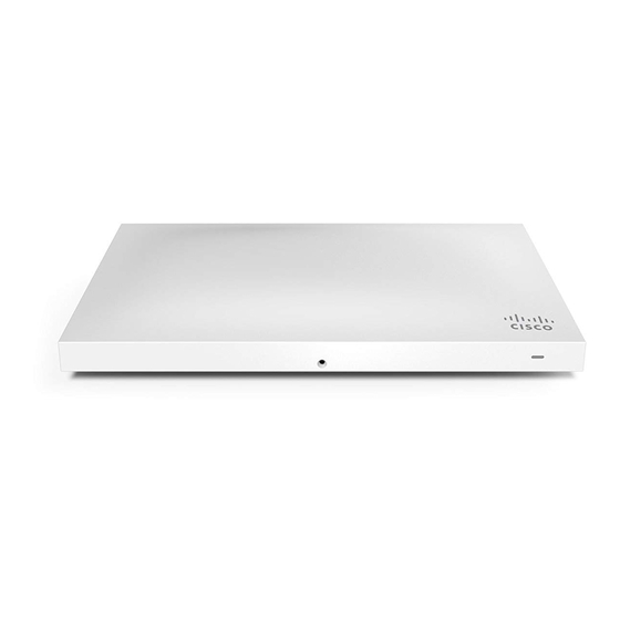
The Cisco Meraki MR34 is a dual-band enterprise class 802.11ac cloud-managed access point. Designed for high
capacity and high density, the MR34 meets the needs of the most demanding environments, and also includes the first
ever cloud-managed third radio dedicated to optimizing the RF environment and securing the airwaves.
Package Contents
The MR34 package contains the following:
• MR34 Cloud-Managed Access Point
• Mount cradle including built-in level tool
1
Advertisement
Table of Contents

Summary of Contents for Cisco MERAKI MR34
-
Page 1: Package Contents
MR34 Installation Guide The Cisco Meraki MR34 is a dual-band enterprise class 802.11ac cloud-managed access point. Designed for high capacity and high density, the MR34 meets the needs of the most demanding environments, and also includes the first ever cloud-managed third radio dedicated to optimizing the RF environment and securing the airwaves. -
Page 2: Understanding The Mr34
• Drop ceiling mount kit • Wall screws, wall screw anchors, and security screws • Spare hardware Understanding the MR34 Your Meraki MR34 has the following features:... - Page 3 The mount cradle has the following features:...
-
Page 4: Security Features
Security Features The MR34 features multiple options for physically securing the access point after installation: 1. Security screw – The accessory kit includes screws that can be used to secure the access point to the mount cradle. Engaging the security screw prevents accidental dislodging and theft. 2. -
Page 5: Pre-Install Preparation
• Blinking Orange - AP can't find uplink The MR34 may be operated in “Run Dark” mode for additional security and to reduce the visibility of the access point. In this mode, the LED will not be illuminated. This mode may be enabled through Meraki dashboard. Pre-Install Preparation You should complete the following steps before going on-site to perform an installation. -
Page 6: Collect Tools
Dynamic Assignment When using DHCP, the DHCP server should be configured to assign a static IP address for each MAC address belonging to a Meraki AP. Other features of the wireless network, such as 802.1X authentication, may rely on the property that the APs have static IP addresses. -
Page 7: Installation Instructions
3. If being used in a mesh deployment, the MR34 should have line of sight to at least two other Meraki devices. For more detailed instructions regarding access point location selection, reference the Meraki Network Design Guide (meraki.cisco.com/library/). Install the MR34 For most mounting scenarios, the MR34 mount cradle provides a quick, simple, and flexible means of mounting your... - Page 8 The mount cradle contains a variety of hole patterns that are customized for each installation scenario. The mounting template (included inbox with mount cradle) should be used to drill holes for wall mounts and also to identify the correct hole patterns in the mount cradle that should be used for each type of mount. The included mount cradle template shows the hole patterns that should be used for each type of mount.
- Page 9 • 2 rubber spacers 1. Attach the T-rail clips to the T-rail by rotating them and snapping them into place as shown. The black foam pads should be compressed slightly after installation. 2. Using the dashed lines on the mount cradle template as a guide, set the proper spacing of the T-rail clips on the T- rail.
-
Page 10: Power The Mr34
4. Attach the mount cradle to the T-rail clips using the mount cradle holes (marked with a “T“). Tip: Pre-assemble rubber spacers and screws to the mount cradle. The mount cradle can then be held with one hand while the other hand holds a screwdriver. If mounting your MR34 to a dropped ceiling, skip to the "Power the MR34"... -
Page 11: Mount The Mr34
Meraki switches are 802.3at compatible and will power the MR34 by default, using LLDP negotiating. When using Cisco switches, an extra step may be required to configure the Cisco switch to use LLDP to communicate with the Meraki MR34; see the following article for more details: https://documentation.meraki.com/MR/Other_Topics/... - Page 12 Then adjust the MR34 to guide the MR34’s bottom slot into the cradle’s bottom tab until it clicks into place. Once in place, the MR34 should be secured to the cradle by using one of the included screws in the cradle’s bottom tab.
-
Page 13: Secure The Mr34
To release the MR34 from the mount cradle, first remove the security screw that secures the MR34 to the cradle’s bottom tab. While holding the MR34 with one hand, press the cradle’s bottom tab upwards, releasing the MR34 from the bottom of the cradle. -
Page 14: Kensington Lock
Security Screw Install the security screw in the lower mount cradle tab. Kensington Lock Attach a Kensington lock cable to the access point at the hard point on the side of the device. Attach the other end of the cable to a secure location, such as a pipe or building fixture. Verify Device Functionality and Test Network Coverage 1.


