Sign In
Upload
Manuals
Brands
Yamaha Manuals
Motorcycle
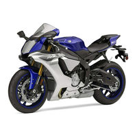
YZF-R1F 2015
Yamaha YZF-R1F 2015 Motorcycle for Sale Manuals
Manuals and User Guides for Yamaha YZF-R1F 2015 Motorcycle for Sale. We have
1
Yamaha YZF-R1F 2015 Motorcycle for Sale manual available for free PDF download: Service Manual
Yamaha YZF-R1F 2015 Service Manual (705 pages)
Brand:
Yamaha
| Category:
Motorcycle
| Size: 42.2 MB
Table of Contents
How to Use this Manual
5
Symbols
6
Table of Contents
7
General Information
9
Model Label
10
Vehicle Identification Number
10
Outline of the Fi System
11
Vehicle View
11
FI System
12
YCC-I (Yamaha Chip Controlled Intake)
14
YCC-T (Yamaha Chip Controlled Throttle)
14
YCC-T/YCC-I System Outline
16
Digital Instrument Panel with TFT Liquid Crystal Display
17
Electronic Control-Related Features
17
6-Axis “IMU” for 3-Dimensional Detection of Machine Motion
18
Five Control Systems to Bring out the Machine’s High Potential
18
Launch Control System (LCS)
19
Lift Control System (LIF)
19
New Traction Control System (TCS)
19
Slide Control System (SCS)
19
Electronic Racing Suspension (ERS)
20
First ABS and Unified Brake System on a Yamaha Supersport Model
20
Quick Shift System (QSS) for Smooth Up-Shifting Even at Full Throttle
20
Systems to Control Machine Motion Characteristics
20
PWR for Power Mode Selection and YAMAHA Ride Control Adopted
21
Rider-Machine Interface: Communication Control Unit (CCU) Adopted
21
Outline of the UBS
22
UBS Diagram
24
UBS Hydraulic Pressure Map
25
Outline of the ABS
26
ABS Layout
27
Brake Force and Vehicle Stability
28
Wheel Slip and Hydraulic Control
28
ABS Operation and Vehicle Control
29
Electronic ABS Features
30
ABS Block Diagram
31
ABS Component Functions
31
Wheel Sensors and Wheel Sensor Rotors
31
ABS Warning Light
32
Hydraulic Control Valve
33
Hydraulic Unit Assembly
33
ABS Control Operation
34
Abs Ecu
34
Normal Braking (ABS Not Activated and UBS Not Activated)
35
UBS and ABS Operation
35
Emergency Braking (ABS Activated and UBS Not Activated)
36
UBS (ABS Not Activated and UBS Activated)
37
UBS (ABS Activated and UBS Activated)
38
ABS Warning Light and Operation
39
ABS and UBS Function
40
Display
41
Glossary
41
Speedometer
41
Information Display
42
Tachometer
42
ERS Indicator (YZF-R1M)
43
GPS Indicator
43
YRC Items LCS/QS/LIF
43
Error Mode
44
Menu Screen
45
Pwr
46
Lcs
47
Lif
47
Qss
47
Ers (Yzf-R1M)
48
“Lap Time”
49
“Logging” (for CCU-Equipped Models)
50
“Maintenance”
50
“Unit”
50
“Shift IND Brightness”
52
“Shift Indicator”
52
“Tach IND Setting”
53
“Display Setting”
54
“Peak Rev IND Setting”
54
“All Reset”
56
“Clock”
56
Aluminium Bolts
57
Gaskets, Oil Seals and O-Rings
57
Important Information
57
Preparation for Removal and Disassembly
57
Replacement Parts
57
Bearings and Oil Seals
58
Circlips
58
Lock Washers/Plates and Cotter Pins
58
Rubber Parts
58
Basic Service Information
59
Quick Fasteners
59
Electrical Parts Handling
60
Electrical System
60
Checking the Connections
62
Checking the Electrical System
62
Special Tools
65
Specifications
75
General Specifications
76
Engine Specifications
77
Chassis Specifications
82
Electrical Specifications
86
Tightening Torques
89
General Tightening Torque Specifications
89
Engine Tightening Torques
90
Chassis Tightening Torques
97
Lubrication Points and Lubricant Types
102
Engine
102
Chassis
103
Lubrication System Chart and Diagrams
106
Engine Oil Lubrication Chart
106
Lubrication Diagrams
108
Cooling System Diagrams
122
Cable Routing
126
Periodic Checks and Adjustments
173
General Maintenance and Lubrication Chart
175
Introduction
175
Periodic Maintenance Chart for the Emission Control System
175
CHECKING the FUEL LINE (Primary Injector)
178
CHECKING the FUEL LINE (Secondary Injector)
178
Checking the Spark Plugs
178
Adjusting the Valve Clearance
179
Checking the Engine Idling Speed
183
Checking the Throttle Body Synchronization
183
Synchronizing the Throttle Bodies
183
Adjusting the Throttle Body Synchronization
184
Checking the Crankcase Breather Hose
185
Checking the Exhaust System
185
Checking the Throttle Body Joints
185
Adjusting the Exhaust Gas Volume
186
Checking the Air Induction System
186
Replacing the Air Filter Element
186
Adjusting the Clutch Lever Free Play
187
Adjusting the Front Disc Brake
188
Checking the Brake Fluid Level
188
Checking the Brake Operation
188
Adjusting the Rear Disc Brake
189
Checking the Front Brake Pads
189
Checking the Rear Brake Pads
189
Bleeding the Hydraulic Brake System (ABS)
190
Checking the Front Brake Hoses
190
Checking the Rear Brake Hose
190
Checking the Tires
191
Checking the Wheels
191
Adjusting the Drive Chain Slack
193
Checking the Swingaram Operation
193
Checking the Wheel Bearings
193
Lubricating the Swingarm Pivot
193
Lubricating the Drive Chain
194
Checking and Adjusting the Steering Head
195
Checking the Chassis Fasteners
196
Checking the Front Fork
196
Checking the Sidestand Switch
196
Checking the Steering Damper
196
Lubricating the Brake Lever
196
Lubricating the Clutch Lever
196
Lubricating the Pedal
196
Lubricating the Sidestand
196
Lubricating the Steering Head
196
ADJUSTING the FRONT FORK LEGS (for YZF-R1)
197
ADJUSTING the PRELOAD of the FRONT FORK LEGS (for YZF-R1M)
198
Compression Damping
198
Adjusting the Damping Force of the Rear Shock Absorber
199
Adjusting the Damping Force of the Front Fork Legs
199
Adjusting the Rear Shock Absorber Assembly
200
Rebound Damping
201
Adjusting the Preload of the Rear Shock Absorber Assembly
202
Checking the Engine Oil Level
203
Changing the Engine Oil
204
Measuring the Engine Oil Pressure
205
Checking the Coolant Level
206
Checking the Cooling System
206
Changing the Coolant
207
Cooling System
208
Adjusting the EXUP Cables
209
Adjusting the Rear Brake Light Switch
210
Checking and Lubricating the Cables
210
Checking the Throttle Grip
210
Adjusting the Headlight Beams
212
Chassis
215
Disassembling the Mudguard Assembly
220
Removing the Electrical Components Tray
229
Installing the Front Side Cowlings
230
REMOVING the FRONT SIDE COWLINGS (for YZF-R1)
230
REMOVING the FRONT SIDE COWLINGS (for YZF-R1M)
230
INSTALLING the FRONT SIDE COWLINGS (for YZF-R1)
231
INSTALLING the FRONT SIDE COWLINGS (for YZF-R1M)
231
Removing the Front Panels
231
INSTALLING the SIDE COVER (Left)
232
REMOVING the SIDE COVER (Left)
232
Installing the ECU (Engine Control Unit)
233
Removing the ECU (Engine Control Unit)
233
General Chassis (3)
234
Removing the Front Cowling Assembly
235
Disassembling the Front Cowling Assembly
236
Removing the Air Intake Duct
237
Installing the Windshield Assembly
238
Removing the Windshield Assembly
238
Checking the Air Intake Duct Valve
239
Checking the Vacuum Line
239
Installing the Air Intake Duct Valve
240
Front Wheel
241
Removing the Front Wheel and Brake Discs
242
Disassembling the Front Wheel
243
Checking the Front Wheel
244
Disassembling the Front Wheel
244
Removing the Front Wheel
244
Assembling the Front Wheel
245
Maintenance of the Front Wheel Sensor and Sensor Rotor
246
Adjusting the Front Wheel Static Balance
247
Installing the Front Wheel (Disc Brake)
248
Rear Wheel Removal
251
Removing the Brake Disc and Rear Wheel Sprocket
252
Disassembling the Rear Wheel
253
Removing the Rear Wheel
254
Checking and Replacing the Rear Wheel Sprocket
255
Checking the Rear Wheel Drive Hub
255
Disassembling the Rear Wheel
255
Assembling the Rear Wheel
256
Adjusting the Rear Wheel Static Balance
257
Installing the Rear Wheel (Disc Brake)
257
Maintenance of the Rear Wheel Sensor and Sensor Rotor
257
Front Brake
260
Removing the Front Brake Pads
260
Removing the Front Brake Master Cylinder
261
Disassembling the Front Brake Master Cylinder
262
Removing the Front Brake Calipers
263
Disassembling the Front Brake Calipers
264
Checking the Front Brake Discs
265
Introduction
265
Replacing the Front Brake Pads
266
Removing the Front Brake Calipers
267
Assembling the Front Brake Calipers
268
Checking the Front Brake Calipers
268
Installing the Front Brake Calipers
269
Assembling the Front Brake Master Cylinder
270
Checking the Front Brake Master Cylinder
270
Installing the Front Brake Master Cylinder
270
Rear Brake
272
Removing the Rear Brake Pads
272
Removing the Rear Brake Master Cylinder
273
Removing the Rear Brake Caliper
274
Disassembling the Rear Brake Caliper
275
Checking the Rear Brake Disc
276
Introduction
276
Replacing the Rear Brake Disc
276
Removing the Rear Brake Caliper
277
Checking the Rear Brake Caliper
278
Assembling the Rear Brake Caliper
279
Installing the Rear Brake Caliper
279
Checking the Rear Brake Master Cylinder
280
The Rear Brake Master Cylinder Installation
281
ABS (Anti-Lock Brake System)
282
Removing the Hydraulic Unit Assembly
282
ABS Components Chart
284
Removing the Hydraulic Unit Assembly
285
Checking the Brake Pipes
286
Checking the Hydraulic Unit Assembly
286
Installing the Hydraulic Unit Assembly
286
Hydraulic Unit Operation Test
287
ABS Reaction-Force Confirmation
289
Checking the ABS Warning Light
290
Handlebars
291
Removing the Handlebars
292
Checking the Handlebars
293
Installing the Handlebars
293
FRONT FORK (for YZF-R1)
296
Removing the Front Fork Legs
296
Disassembling the Front Fork Legs
297
DISASSEMBLING the FRONT FORK LEGS (for YZF-R1)
298
REMOVING the FRONT FORK LEGS (for YZF-R1)
298
ASSEMBLING the FRONT FORK LEGS (for YZF-R1)
300
CHECKING the FRONT FORK LEGS (for YZF-R1)
300
INSTALLING the FRONT FORK LEGS (for YZF-R1)
304
FRONT FORK (for YZF-R1M)
307
DISASSEMBLING the FRONT FORK LEGS (for YZF-R1M)
309
REMOVING the FRONT FORK LEGS (for YZF-R1M)
309
CHECKING the FRONT FORK LEGS (for YZF-R1M)
310
ASSEMBLING the FRONT FORK LEGS (for YZF-R1M)
311
INSTALLING the FRONT FORK LEGS (for YZF-R1M)
314
Removing the Lower Bracket
317
Steering Head
317
Checking the Steering Head
319
Removing the Lower Bracket
319
Checking the Steering Damper
320
Installing the Steering Head
320
Rear Shock Absorber Assembly Removal
321
Disposing of a Rear Shock Absorber
325
Removing the Rear Shock Absorber Assembly
325
Checking the Connecting Arm and Relay Arm
326
Checking the Rear Shock Absorber Assembly
326
Disassembling the Rear Shock Absorber Assembly
326
Assembling the Rear Shock Absorber Assembly
327
Installing the Relay Arm
327
Installing the Rear Shock Absorber Assembly
328
Removing the Swingarm
329
Checking the Swingram
330
Removing the Swingarm
330
Installing the Swingram
331
Removing the Drive Chain
333
Checking the Drive Chain
334
Checking the Rear Wheel Drive Hub
335
Checking the Rear Wheel Sprocket
335
Installing the Drive Chain
336
Adjusting the Shift Pedal
337
Engine
339
Engine Inspection
342
Measure the Compression Pressure
342
Engine Removal
344
Removing the Muffler and Exhaust Pipe
344
Disconnecting the Leads and Hoses
346
Installing the Engine
348
Removing the Engine
348
Installing the Exhaust Pipe and Muffler
349
Camshafts
350
Removing the Cylinder Head Cover
350
Removing the Camshafts
351
Removing the Timing Chain and Timing Chain Guide
352
Removing the Rocker Arms
353
Removing the Camshafts
354
Checking the Camshafts
355
Removing the Rocker Arms and Rocker Arm Shafts
355
Checking the Rocker Arms and Rocker Arm Shafts
357
Checking the Timing Chain and Camshaft Sprocket
357
Checking the Timing Chain Guides
358
Checking the Timing Chain Tensioner
358
Assembling the Timing Chain Cover
359
Installing the Rocker Arms and Rocker Arm Shafts
359
Installing the Timing Chain Cover
359
Installing the Camshafts
360
Removing the Cylinder Head
364
Installing the Cylinder Head
365
Removing the Valves and Valve Springs
367
Checking the Valves and Valve Guides
369
Removing the Valves
369
Valves and Valve Springs
369
Checking the Valve Seats
371
Checking the Valve Spring Seat
373
Installing the Valves
374
Generator
376
Removing the Stator Coil and Generator Rotor
376
Installing the Generator
377
Removing the Generator
377
Removing the Starter Clutch
379
Checking the Starter Clutch
380
Installing the Starter Clutch
380
Electric Starter
382
Removing the Starter Motor
382
Disassembling the Starter Motor
383
Checking the Starter Motor
384
Assembling the Starter Motor
385
Removing the Oil Pan and Oil Pump
386
Disassembling the Oil Pump
388
Checking the Sprocket and Chain
389
Removing the Oil Pan
389
Checking the Oil Pump
390
Checking the Relief Valve
390
Assembling the Oil Pump
391
Checking the Oil Delivery Pipes
391
Checking the Oil Strainer
391
Installing the Oil Pump
391
Installing the Oil Pan
393
Clutch
394
Removing the Clutch Cover
394
Removing the Pull Lever Shaft
395
Removing the Clutch
396
Removing the Clutch
397
Checking the Clutch Plates
398
Checking the Friction Plates
398
Checking the Clutch Boss
399
Checking the Clutch Housing
399
Checking the Clutch Springs
399
Checking the Pressure Plate
399
Checking the Primary Drive Gear
400
Checking the Primary Driven Gear
400
Checking the Pull Lever Shaft and Pull Rod
400
Installing the Clutch
400
Removing the Shift Shaft and Stopper Lever
403
Shift Shaft
403
Checking the Shift Shaft
404
Checking the Stopper Lever
404
Installing the Shift Shaft
404
Crankcase
405
Removing the Crankcase Breather Cover and Switches
405
Separating the Crankcase
407
Assembling the Crankcase
408
Checking the Crankcase
408
Disassembling the Crankcase
408
Installing the Crankcase Breather Cover
410
Installing the Oil Pressure Switch
410
Installing the Gear Position Sensor
411
Removing the Connecting Rods and Pistons
412
Connecting Rods and Pistons
413
Removing the Connecting Rods and Pistons
413
Checking the Cylinder and Piston
414
Checking the Piston Rings
415
Checking the Piston Pin
416
Checking the Connecting Rods
417
Installing the Connection Rod and Piston
419
Removing the Crankshaft and Balancer Shaft
425
Checking the Crankshaft
426
Checking the Oil Nozzles
426
Crankshaft and Balancer Shaft
426
Removing the Crankshaft and Balancer Shaft
426
Checking the Balancer Shaft
428
Installing the Crankshaft
429
Installing the Balancer Assembly
430
Removing the Transmission, Shift Drum Assembly, and Shift Forks
431
Transmission
431
Disassembling the Main Axle Assembly
432
Checking the Shift Forks
435
Removing the Transmission
435
Assembling the Main Axle and Drive Axle
436
Checking the Shift Drum Assembly
436
Checking the Transmission
436
Installing the Transmission
437
Cooling System
439
Removing the Radiator
440
Checking the Radiator
441
Installing the Radiator
442
Removing the Oil Cooler
443
Checking the Oil Cooler
444
Installing the Oil Cooler
444
Removing the Thermostat
445
Assembling the Thermostat Assembly
446
Checking the Thermostat
446
Installing the Thermostat Assembly
446
Removing the Thermostat Assembly
446
Removing the Water Pump
448
Disassembling the Water Pump
449
Assembling the Water Pump
450
Checking the Water Pump
450
Installing the Water Pump
451
Fuel System
453
Removing the Fuel Tank
454
Checking the Fuel Pump Operation
455
Removing the Fuel Pump
455
Installing the Fuel Pump
456
Installing the Fuel Tank
456
Air Filter Case
457
Removing the Air Filter Case and Secondary Injectors
457
Checking the Secondary Injectors
458
Checking the Secondary Injectors (before Removing)
458
Removing the Air Filter Case
458
Removing the Fuel Hose (Primary Injector Joint Side and Secondary Injector Joint Side)
458
Checking the Air Filter Case Seal
459
Checking the Intake Funnel
459
Checking the Secondary Injectors
459
Removing the Intake Funnel Assembly
459
Checking the Intake Funnel Operation
460
Installing the Intake Funnel and Air Filter Case
460
Installing the Secondary Injectors
460
Installing the Air Filter Case Cover
461
Installing the Fuel Hose (Primary Injector Joint Side and Secondary Injector Joint Side)
461
Removing the Throttle Bodies
462
Removing the Sensors
464
Checking and Cleaning the Throttle Bodies
465
Checking the Primary Injectors (before Removing)
465
Checking the Injector Pressure
467
Installing the Primary Injectors
467
Replacing the Throttle Bodies
467
Checking the Fuel Pressure
468
Adjusting the Throttle Position Sensor
469
Adjusting the Accelerator Position Sensor
470
Air Induction System
472
Removing the Air Cut-Off Valve Assembly and Reed Valves
474
Checking the Air Induction System
476
Installing the Air Induction System
477
Electrical System
479
Ignition System Circuit Diagram
482
Engine Stopping Due to Sidestand Operation
486
Ignition System Troubleshooting
487
Electric Starting System Circuit Diagram
490
Starting Circuit Cut-Off System Operation
494
Electric Starting System Troubleshooting
495
Charging System Circuit Diagram
498
Charging System Troubleshooting
502
Lighting System Circuit Diagram
504
Lighting System Troubleshooting
508
Signaling System Circuit Diagram
510
Signaling System Troubleshooting
514
Cooling System Circuit Diagram
520
Cooling System Troubleshooting
524
Fuel Injection System Circuit Diagram
526
ECU Self-Diagnostic Function
530
Checking the Engine Trouble and System Warning Light
530
Troubleshooting Method (ECU)
531
ECU Detects an Abnormal Signal from a Sensor
531
Yamaha Diagnostic Tool
533
Troubleshooting Details (ECU)
535
Gear Position Sensor: Open or Short Circuit Detected
535
Cylinder Identification Sensor: no Normal Signals Received
536
Intake Air Pressure Sensor: Open or Short Circuit Detected
539
Intake Air Pressure Sensor: Hose System Malfunction
540
Throttle Position Sensor: Open or Short Circuit Detected
541
EXUP Servo Motor: Open or Short Circuit Detected
542
EXUP Servo Motor: Stuck EXUP Servo Motor Is Detected
543
Sidestand Switch: Break/Disconnection of Blue/Yellow Lead of the ECU
544
Intake Air Pressure Sensor or Atmospheric Pressure Sensor
545
Coolant Temperature Sensor: Open or Short Circuit Detected
547
Intake Air Temperature Sensor: Open or Short Circuit Detected
548
Atmospheric Pressure Sensor: Open or Short Circuit Detected
549
O2 Sensor 1: no Normal Signals Are Received from the O2 Sensor 1
552
Latch up Detected
552
Cylinder-#1 Ignition Coil
553
Cylinder-#2 Ignition Coil
554
Cylinder-#3 Ignition Coil
555
Cylinder-#4 Ignition Coil
556
Primary Injector: Open or Short Circuit Detected
558
Secondary Injector: Open or Short Circuit Detected
559
IMU (Inertial Measurement Unit): no Normal Signals Are Received
561
Rear Wheel Sensor: no Normal Signals Are Received
562
Neutral Switch: Open or Short Circuit Is Detected
563
Clutch Switch: Open or Short Circuit Is Detected
563
Fuel System Voltage: Incorrect Voltage Supplied to the Fuel Injector
569
EEPROM Fault Code Number: an Error Is Detected
570
Malfunction in ECU Internal Circuit
572
Charging Voltage Is Abnormal
573
Faulty ECU Memory
574
Accelerator Position Sensor: Open or Short Circuit Detected
574
YCC-T Drive System: Malfunction Detected
575
Steering Damper Solenoid: Open or Short Circuit Detected
577
O2 Sensor 1: no Normal Signals Are Received from the O2 Sensor 2
578
No Normal Signals Are Received from the Front Front Wheel Sensor
579
Signals Cannot be Transmitted between the ECU and Multi-Function Meter
581
The ECU Cannot Receive Fault Signals from the IMU
582
No Signal Exchange between ECU and IMU
583
Fuel Pump System Circuit Diagram
584
Fuel Pump System Troubleshooting
588
Immobilizer System Circuit Diagram
590
Immobilizer System - General Information
594
Code Re-Registering Key Registration
595
Standard Key Registration
596
Voiding the Standard Key Code
596
Immobilizer System Troubleshooting
598
Immobilizer System Indicator Light Fault Code Indication
599
ABS (Anti-Lock Brake System) Circuit Diagram
600
ABS Coupler Location Chart
606
Maintenance of the ABS ECU
608
ABS Troubleshooting
608
ABS Operation When the ABS Warning Light Comes on
608
ABS ECU Self-Diagnosis and Servicing
608
Rear Wheel Sensor (Intermittent Pulses or no Pulses)
614
ABS (Anti-Lock Brake System) - Fault Code Table
614
Front Wheel Sensor (Intermittent Pulses or no Pulses)
614
Front Wheel Sensor (Abnormal Pulse Period)
615
Rear Wheel Sensor (Abnormal Pulse Period)
615
Front Wheel Sensor (Open or Short Circuit)
615
Hydraulic Unit Assembly (Defective ABS Solenoid Power Circuit)
615
Rear Wheel Sensor (Missing Pulses)
616
Voltage of ABS ECU Power Supply Is High
616
Front Wheel Sensor (Missing Pulses)
616
Front Wheel ABS (Intermittent Wheel Speed Pulses)
616
ABS (Anti-Lock Brake System) Final Check
632
Electronically Adjustable Suspension System
634
Maintenance of the SCU (Suspension Control Unit)
636
SCU (Suspension Control Unit) Self-Diagnostic Function
636
SCU Troubleshooting Method
636
SCU Detects an Abnormal Signal from a Sensor
636
The Engine Trouble and System Warning Light Comes on
637
SCU Troubleshooting Details
637
Electrical Components
654
Checking the Switches
658
Checking the Fuses
661
Replacing the ECU (Engine Control Unit)
661
Checking and Charging the Battery
662
Checking the Relays
665
Checking the Ignition Coils
667
Checking the Ignition Spark Gap
667
Checking the Stator Coil
668
Checking the Starter Motor Operation
668
Checking the Crankshaft Position Sensor
668
Checking the Rectifier/Regulator
669
Checking the Horn
670
Checking the Fuel Sender
670
Checking the Fuel Level Warning Light
671
Checking the Radiator Fan Motors
671
Checking the Coolant Temperature Sensor
671
Checking the Throttle Position Sensor
672
Checking the Accelerator Position Sensor
672
Checking the Throttle Servo Motor
673
Checking the Air Induction System Solenoid
673
Checking the Atmospheric Pressure Sensor
674
Checking the Cylinder Identification Sensor
674
Checking the Intake Air Pressure Sensor
675
Checking the Intake Air Temperature Sensor
675
Checking the Intake Solenoid
676
Checking the Steering Damper Solenoid
676
Checking the Wheel Switch
677
Checking the Fuel Injectors
677
Troubleshooting
679
Self-Diagnostic Function and Diagnostic Code Table (ECU)
684
Communication Error with the Meter
685
Diagnostic Code: Sensor Operation Table
686
Diagnostic Code: Actuator Operation Table
689
Event Code Table
692
Wiring Diagram Items
695
Wiring Diagram
701
Advertisement
Advertisement
Related Products
Yamaha YZFR1FC
Yamaha YZFR1F
Yamaha YZFR1W 2007
Yamaha YZF-R1 1998
Yamaha YZF-R1SVC
Yamaha YZFR1R1C 2024
Yamaha YZFR1MR 2024
Yamaha YZFR1GC 2015
Yamaha YZFR1M1C 2020
Yamaha YZF-R1 98
Yamaha Categories
Motorcycle
Musical Instrument
Electronic Keyboard
Receiver
Amplifier
More Yamaha Manuals
Login
Sign In
OR
Sign in with Facebook
Sign in with Google
Upload manual
Upload from disk
Upload from URL