Sign In
Upload
Manuals
Brands
Yamaha Manuals
Receiver
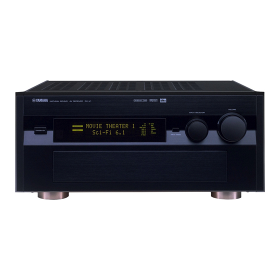
RX-V1
Yamaha RX-V1 Manuals
Manuals and User Guides for Yamaha RX-V1. We have
2
Yamaha RX-V1 manuals available for free PDF download: Service Manual, Owner's Manual
Yamaha RX-V1 Owner's Manual (95 pages)
Natural Sound AV Receiver
Brand:
Yamaha
| Category:
Receiver
| Size: 3.74 MB
Table of Contents
Table of Contents
5
Safety Instructions
2
Comparing Surround Technologies
7
Dolby Digital and Dolby Digital Surround EX
7
DTS and DTS es
7
Features
7
Introduction
7
Built-In 8-Channel Power Amplifier
8
Custom Installation Facility
8
Getting Started
9
Digital Sound Fields (DSP)
8
Multi-Function Remote Control
8
Various Input and Output Jacks
8
Checking the Package Contents
9
Installing Batteries in the Remote Control
9
Using the Remote Control
9
Controls and Functions
10
Front Panel
10
Opening and Closing the Front Panel Door
11
Remote Control
12
Sleep Timer
13
Front Panel Display
14
Rear Panel
15
Preparations
16
Speaker System Configurations
17
Eight or Seven Speaker Configuration -Full Cinema DSP
17
Six Speaker Configuration -Hi Fi DSP
17
Five Speaker Configuration -Standard 5.1 Channel
17
Four Speaker Configuration -Minimum Requirement
17
Speaker Placement
18
Placing the Main Speakers
18
Placing the Center Speaker
18
Placing the Front Effect, Rear and Rear Center Speakers
18
When You Use a Projection Screen
18
Placing the Subwoofers
18
Hookups
19
Connecting to Digital Jacks
19
About the Video Jacks
19
About the RF (AC-3) Signal Input Jack
19
Connecting Audio Components
20
Connecting a Turntable
20
Connecting a Tape Deck
21
Connecting Video Components
22
Connecting a Vcr
23
Connecting a DVD Player
23
Connecting a Video Monitor
23
Connecting Speakers
24
Impedance Selector Switch
26
Connecting External Amplifiers
27
Connecting an External Decoder
28
Connecting the Ac Power Cord
28
Connecting Power Supply Cords
28
Connecting the Antennas
29
Connecting the am Loop Antenna
29
On-Screen Displays (OSD)
30
OSD Modes
30
Selecting the OSD Mode
30
Speaker Settings
31
Before You Begin
31
Speaker Output Levels
31
Dolby Surround Test
32
DSP Test
33
Basic Operation
34
Basic Playback
35
Power Control
35
Selecting a Source
36
Input Modes and Indications
37
Selecting a Sound Field Program
38
Normal Stereo Reproduction
38
AM/FM Tuner
39
Manual Tuning
39
Automatic Tuning
39
Presetting Stations
40
Tuning to Preset Stations
42
Exchanging Preset Stations
42
Basic Recording
43
Preparations
43
Advanced Operation
44
SET MENU Items
45
Operating the SET MENU
46
1 SPEAKER SET (1A. CENTER SP to 1G. MAIN LEVEL)
47
2 Low Freq. Test
50
3 DOLBY D. SET (Dolby Digital Set)
51
4 Dts Set
52
5 Sp Delay Time
52
6 Audio Delay
52
7 CENTER GEQ (Center Graphic Equalizer)
53
8 REAR CT GEQ (Rear Center Graphic Equalizer)
53
9 Cinema Eq
54
12. 6.1/Es Auto
55
10 HP TONE CTRL (Headphone Tone Control)
55
11 PARAMETER INI (Parameter Initialization)
55
13 Memory Guard
56
14 CMPNT-V INPT (Component Video Input)
56
15 Input Mode
56
16 Input Rename
57
17 Dimmer
57
18 Zone 2 Set
57
Remote Control Features
58
Using the Remote Control
58
Source Select
59
Each Component Control Area
60
Operating a Tuner (TUNER Area)
60
Operating a Tape Deck (TAPE Area)
60
Operating a CD Player (CD Area)
61
Operating an MD Recorder (MD Area)
61
Operating an LD Player (LD Area)
62
Operating a DVD Player (DVD Area)
62
Operating a VCR (VCR1/VCR2/VCR3 Area)
63
Operating a TV or Digital TV (D-TV Area)
63
Operating a Cable or Satellite TV Tuner (CBSAT Area)
64
Free Area (OPTN and PHONO Areas)
64
Seting the Manufacturer Code in the Remote Control
65
Programming a New Remote Control Function
66
Using the Macro Feature
67
Changing the Source Name in the Display Window
69
Clearing a Learned Function or Macro
69
Clearing Learned Functions, Macros, Renamed Displays, and Manufacturer Setups
70
Setting the Sleep Timer
71
Adjusting the Levels of the Effect Speakers
71
Zone 2
72
Connections
72
Remote Control in ZONE 2
73
Additional Information
74
Digital Sound Field Processing (DSP)
75
Understanding Sound Fields
75
Recreating a Sound Field
75
E/R (Early Reflection)
75
4Ch REV. (Four Channel Reverberation)
75
Illustration of the Virtual Sound Sources and Echo Patterns
75
Hi-Fi DSP-Sound Field Program
76
Program Group 1 : Concert Hall 1
76
Program Group 2 : Concert Hall 2
76
Program Group 3 : Church
76
Program Group 4 : Jazz Club
76
Program Group 5 : Rock Concert
76
Program Group 6 : Entertainment
76
Cinema-Dsp
77
The Sound Design of CINEMA-DSP Sound Field Programs
77
Sound Field Images of the CINEMA-DSP Programs
77
Movie Theater Programs
78
CINEMA-DSP Sound Field Program
79
Program Group 7 : Concert Video 1
80
Program Group 8 : Concert Video 2
80
Program Group 9 : TV Theater
80
Program Group 10 : Movie Theater 1
80
Program Group 11 : Movie Theater 2
80
Program Group 12 : Dolby/Dts Surround
80
Sound Field Program Parameter Editing
81
Changing Parameter Settings
81
Resetting a Parameter to the Factory Preset Value
81
Digital Sound Field Parameter Descriptions
82
EFCT TRIM (Effect Trim)
82
INIT. DLY (Initial Delay)
82
INIT. DLY (Presence Initial Delay)
82
RC. INIT. DLY (Rear Center Initial Delay)
82
INIT. DLY (Surround Initial Delay)
82
DLY (Surround Delay)
83
Room Size
83
RC. ROOM SIZE (Rear Center Room Size)
84
ROOM SIZE (Surround Room Size)
84
Liveness
84
LIVENESS (Surround Liveness)
84
RC LIVENESS (Rear Center Liveness)
84
REV. TIME (Reverberation Time)
85
REV. DELAY (Reverberation Delay)
85
REV. LEVEL (Reverberation Level)
85
Appendix
86
Troubleshooting
87
Reference Chart for the INPUT and OUTPUT Jacks
91
CINEMA - EQ Frequency Characteristics
91
Specifications
92
Quick Reference Card
94
Advertisement
Yamaha RX-V1 Service Manual (104 pages)
AV AMPLIFIER/AV RECEIVER
Brand:
Yamaha
| Category:
Amplifier
| Size: 8.92 MB
Table of Contents
Table of Contents
1
Important Notice
1
To Service Personnel
2
Safety Precautions
2
Front Panels DSP-AX1 and RX-V1
3
Specifications
4
Dimensions
5
Set Menu Table
6
Superimposing
6
Parameter Table
7
Removal of Bottom Cover
8
Removal of Top Cover
8
Internal View
8
Disassembly Procedures
8
Removal of DSP P.C.B.
9
Removal of Main P.C.B.
9
Self Diagnosis Function
10
Starting DIAG
11
Starting DIAG in the Protection Cancel Mode
11
Canceling DIAG
11
Display at the Start of DIAG
12
Opening Message
12
DIAG Menu Display
12
DC PRT Display
13
TMP PRT Display
13
PS PRT Display
13
PROTECTION Display
13
Operation Procedure of DIAG Menu and SUB-MENU
14
Functions During DIAG Being Set
14
Initial Settings Used to Start DIAG Function
14
Details of DIAG Menu
15
DSP through
15
Decoder THR.
17
RAM through
18
PRO Logic
20
Bypass
22
Speakers Set
23
Display CHK
24
Rs-232C
25
Manual Test
25
Preset
26
Preset Stations
26
Fan/Ad
27
If Status
28
DSP RAM Check
30
Sum/Ver /Port
30
Port to Check Functions of the Main Microprocessor
31
Port to Check Functions of the REC out
31
Specifications
31
Idling Current Adjustment
32
Test Point
32
AMP Adjustments
32
Dummy Antenna
33
Measuring Instruments
33
Tuner Adjustments (RX-V1 Only)
33
FM Adjustment
34
Before Adjustment
34
Connection Diagram (Measuring Instruments)
34
AM Adjustment
36
Display Data
37
PIN Connection
37
Grid Assignment
37
Anode Connection
38
IC27 : M30624FGFP (P.C.B. FUNCTION) 16 Bit-COM (Main CPU)
39
IC Data
39
IC1 : M30624FGFP (P.C.B. DSP)16 Bit COM (Sub CPU)
41
IC2 : YSD917 (P.C.B. DSP) DIR5 (Digital Format Interface Receiver)
43
IC5 : YSS908-F (P.C.B. DSP) Ac3Dav
44
Top View
44
IC6 : YSS918 (P.C.B. DSP) Ac3D2A
47
IC7,8: YSS910-SDSP6 (Digital Audio Processor)
50
IC24: PM4007A (P.C.B. DSP)AC-3 RF Demodulator
51
IC12: M35013-079SP (P.C.B. VIDEO) Superimpose
54
Block Diagram
55
Block Diagram (Tuner: RX-V1 Only)
57
PIN Connection Diagram
57
Ics
57
Transistors
57
Schematic Diagram (DSP(1)
58
Schematic Diagram (Function)
60
Schematic Diagram (Main)
61
Schematic Diagram (DSP (2)
62
Schematic Diagram (Video)
63
Schematic Diagram (Sub Trans)
66
Schematic Diagram (Tuner: RX-V1 Only)
69
Electrical Parts
70
Parts List
70
P.C.B. Main
71
P.C.B. Main and Video
75
P.C.B. Video
76
P.C.B. Sub Trans
79
P.C.B. Function
81
P.C.b. Dsp
87
P.C.B. Tuner (Lead Type)
94
P.C.B. Tuner (Lead Type and SMD)
95
Chip Resistor
96
Exploded View
97
Mechanical Parts
98
Remote Control Transmitter
100
Schematic Diagram
100
Key Arrangement
101
Initial Code of Yamaha
101
Key Type Table
102
Key Function of K22-K60/K22
102
Initial Macro Setup
102
Parts List for Carbon Resistors
103
Advertisement
Related Products
Yamaha RX-V1000RDS
Yamaha RX-V1900BL
Yamaha RX-V1000
Yamaha RX-V1300
Yamaha RX-V1500
Yamaha RX-V1400
Yamaha RX-V1600
Yamaha RX-V1GL
Yamaha RX-V1050
Yamaha RX-V10MKII
Yamaha Categories
Motorcycle
Musical Instrument
Electronic Keyboard
Receiver
Amplifier
More Yamaha Manuals
Login
Sign In
OR
Sign in with Facebook
Sign in with Google
Upload manual
Upload from disk
Upload from URL