Sign In
Upload
Manuals
Brands
Yamaha Manuals
Music Mixer
PM1D Manager V2
Yamaha PM1D Manager V2 Manuals
Manuals and User Guides for Yamaha PM1D Manager V2. We have
8
Yamaha PM1D Manager V2 manuals available for free PDF download: Operating Manual, Supplementary Manual, Owner's Manual, Installation Manual, Overview
Yamaha PM1D Manager V2 Operating Manual (630 pages)
Digital Audio Mixing System Software V1.41
Brand:
Yamaha
| Category:
Recording Equipment
| Size: 26.84 MB
Table of Contents
Operating Manual (Start-Up)
20
Effect Parameters
3
Operating Notes
16
Table of Contents
20
About the "CS1D Operating Manual (Start-Up)
22
Introduction
22
Printing Conventions in "CS1D Operating Manual (Start-Up)
22
Introducing the Various Components
23
Terms Used in the "CS1D Operating Manual (Start-Up)
25
Connections (Standard Mode)
27
Connecting the Console and Engine (Standard Mode)
27
Connecting an Analog Input/Output Unit to the Engine
29
Mode)
30
Connecting a Digital Input/Output Unit to the Engine (Standard Mode)
30
Connections (Mirror Mode)
31
Connecting the Console and Engines (Mirror Mode)
31
Connecting an Analog Input/Output Unit to the Engines (Mirror Mode)
33
Connecting a Digital Input/Output Unit to the Engines (Mirror Mode)
34
Turning on the Power and Verifying the Connections
35
Turning on the Power
35
Checking the Status of each Device (Standard Mode)
36
Checking the Engine (Standard Mode)
36
Checking the Analog Input Unit (Standard Mode)
37
Checking the Analog Output Unit (Standard Mode)
38
Digital Input/Output Unit (Standard Mode)
38
Checking the Status of each Device (Mirror Mode)
39
Engines (Mirror Mode)
39
Checking the Analog Input Unit (Mirror Mode)
40
Checking the Analog Output Unit (Mirror Mode)
41
Checking the Digital Input/Output Unit (Mirror Mode)
42
Basic Settings (Standard Mode)
43
Selecting the Operation Mode (Standard Mode)
43
Setting the Word Clock (Standard Mode)
45
Basic Settings (Mirror Mode)
47
Selecting the Operation Mode (Mirror Mode)
47
Setting the Word Clock (Mirror Mode)
49
Checking the Operation of Input Units
51
Preparations for Checking
51
Connect the Monitor System
52
Connect an Input Source
53
Patch the Input Unit to an Input Channel
54
Monitor the Input Signal
57
Checking the Operation of an Output Unit
59
Preparations for Checking
59
Connect the Monitor System
60
Connect an Input Source
61
Patch the Input Unit to an Input Channel
62
Patch the STEREO a Channel to an Output Unit
63
Send the Input Signals of Input Channels 1/2 to the STEREO Bus
65
Turn off the Power
67
Operating Manual (Basic Operation)
69
Chapter 1. Introduction
73
About the "CS1D Operation Manual (Basic Operation)
73
Printing Conventions in the "CS1D Operation Manual (Basic Operation)
73
Component Structure
74
Full-Digital/Separate Type SR Mixing System
74
Overview of the PM1D System
74
Signal Flow in the PM1D System
76
Number of Inputs/Outputs and Channel Structure
78
MIX Buses/Matrix Buses
80
Scene Memories/Libraries
80
Word Clock Synchronization
80
Chapter 2. The User Interfaces of the CS1D
81
About the User Interfaces
81
User Interfaces Within the Display
81
User Interface on the Top Panel of the CS1D
83
External User Interfaces
84
Various Basic Operations
86
Click
86
Drag
86
Drag and Drop
87
Scroll
87
Accessing the Desired Screen
88
Button Operations
89
Moving the Cursor
90
Adjusting the Value of a Knob or Fader
91
Assigning a Name
92
Chapter 3. Audio Connections and Patching
94
Audio Connections
94
Audio Connections for an Analog Input Unit
94
Audio Connections for an Analog Output Unit
96
Audio Connections for a Digital Input/Output Unit
97
Audio Connections for the Console
98
Patching
100
Input Channel Patching
100
Output Channel Patching
102
Chapter 4. Basic Operation for Input Channels
104
About Input Channels
104
Blocks Used to Control Input Channels
104
Changing the Channel Assignments
105
Basic Operation INPUT Blocks/St in Block
106
INPUT Block/St in Block Controls and Functions
106
Head Amp Settings
108
Sending a Signal from an Input Channel to a STEREO Bus
110
Sending a Signal from an Input Channel to a MIX Bus
111
Pairing Settings
115
Basic Operation in the SELECTED INPUT CHANNEL Block
116
Controls and Functions of the SELECTED INPUT CHANNEL Block
116
Head Amp Settings
118
Sending Signals from an Input Channel to the STEREO Bus
119
Sending Signals from an Input Channel to a MIX Bus
121
Using the Delay
123
Using the Compressor
124
Using the Noise Gate
127
Using the 4 Band EQ/HPF
129
Chapter 5. Basic Operation for Output Channels
131
About the Output Channels
131
Blocks Used to Control the Output Channels
131
Switching the Channel Assignments
132
Basic Operation of the MIX OUTPUT Block
133
Controls and Functions of the MIX OUTPUT Block
133
Sending a Signal from a MIX Channel to an Output Unit
134
Sending a Signal from a MIX Channel to a MATRIX Bus
135
Sending a Signal from a MIX Channel to the STEREO Bus
137
Pairing MIX Channels
138
Basic Operation of the MATRIX OUTPUT Block
141
Controls and Functions of the MATRIX OUTPUT Block
141
Sending a Signal from a MATRIX Channel to an Output Unit
141
Pairing MATRIX Channels
142
Basic Operation of the STEREO OUTPUT Block
144
Controls and Functions of the STEREO OUTPUT Block
144
Sending a Signal from a STEREO A/B Channel to an Output Unit
145
Basic Operation of the SELECTED OUTPUT CHANNEL Block
146
Controls and Functions of the SELECTED OUTPUT CHANNEL Block
146
Sending a Signal from an Output Channel to an Output Unit
147
Sending a Signal from a MIX Channel to a MATRIX Bus/Stereo Bus
149
Sending a Signal from the STEREO a Channel to the MATRIX Bus
151
Delay Settings
152
Compressor Settings
153
Band EQ/HPF Settings
155
Chapter 6. Insert and Direct out
157
Insert
157
Connecting the External Device to be Inserted
157
Inserting into an Input Channel
158
Inserting into an Output Channel
161
Direct out
163
Direct out Connections
163
Directly Outputting an Input Channel Signal
163
Chapter 7. DCA Groups/Mute Groups
165
DCA Groups
165
Assigning a Channel to a DCA Group
165
Controlling a DCA Group
167
Mute Groups
168
Assigning Input Channels to a Mute Group
168
Assigning Output Channels to a Mute Group
169
Controlling a Mute Group
170
Chapter 8. Scene Memory
172
About Scenes
172
Scene Memory Operations
174
Storing a Scene
174
Recalling a Scene
175
Using PREVIEW Mode
176
Directly Recalling a Scene
177
Chapter 9. Recall Safe/Mute Safe
178
Recall Safe
178
Using the Console to Set/Defeat Recall Safe
178
Using the Screen to Set/Defeat Recall Safe
179
Mute Safe
180
Using the Console to Set/Defeat Mute Safe
180
Using the Screen to Set/Defeat Mute Safe
181
Chapter 10. Monitor
182
Basic Operation of the MONITOR A/MONITOR B Section
182
About MONITOR A/MONITOR B
182
Controls and Functions of the MONITOR A/MONITOR B Sections
183
Using the MONITOR a Section to Monitor a Signal
183
Using the MONITOR B Section to Monitor a Signal
185
Using the Cue/Solo Function
187
Cue Mode and solo Mode
187
Cue/Solo Groups
188
Controls and Functions of the CUE Section
189
Using the Cue Function
189
Using the solo Function
191
Chapter 11 . Talkback/Oscillator
192
Talkback
192
Oscillator
194
Chapter 12. Internal Effects
196
About the Internal Effects of the PM1D System
196
Patching an Internal Effect
197
Using an Internal Effect Via the MIX Bus
197
Inserting an Internal Effect into a Channel
200
Basic Operation of the Effect Screen
202
Editing Effect Parameters
202
Recalling Effect Data from the Library
203
Storing Effect Data to the Library
205
Chapter 13. Graphic EQ
206
Inserting a Graphic EQ into a Channel
206
Controlling a Graphic EQ
208
Controlling a Graphic EQ from the Display
208
Controlling a Graphic EQ from the DCA Faders
209
Chapter 14. MIDI/Time Code
211
Using MIDI Program Changes to Control Events
211
Using Time Code to Control Events
214
Chapter 15. Using a Memory Card to Save/Load Data
216
Saving a File Onto a Memory Card
216
Loading a File from a Memory Card
218
Chapter 16. Various Settings
220
Initial Settings for the Console
220
Setting the Internal Calendar and Clock
222
Specifying the Metering Points
223
Input Channel Metering Point
223
Output Channel Metering Point
224
User Defined Function Settings
225
Reference Manual (Hardware)
229
How the "CS1D Reference Manual (Hardware)" Is Organized
231
Printing Conventions in the "CS1D Reference Manual
233
INPUT Block
234
INPUT Block Channel Assignments
235
ST in Block
243
Channel Assignments for the ST in Block
243
SELECTED INPUT CHANNEL Block
249
48/Ø/Insert (+48/Phase/Insert) Section
251
INPUT Section
252
DELAY Section
252
MIX SEND Section
253
COMPRESSOR Section
255
NOISE GATE Section
257
EQUALIZER Section
259
STEREO Section
260
GAIN Section
261
ATTENUATOR Section
261
FADER Section
262
DCA Section
263
SAFE Section
264
CHANNEL SELECT Section
264
GLOBAL CONTROL Section
266
Display
269
MIX OUTPUT Block
270
Channel Assignments in the MIX OUTPUT Block
271
MIX Channel Section
272
MIX LAYER Section
275
MATRIX OUTPUT Block
276
MATRIX OUTPUT Block Channel Assignments
277
MATRIX Channel Section
278
MATRIX LAYER Section
281
STEREO OUTPUT Block
282
SELECTED OUTPUT CHANNEL Block
286
DELAY Section
289
COMPRESSOR Section
290
EQUALIZER Section
292
OUTPUT Section
293
DCA Section
295
SAFE Section
296
CHANNEL SELECT Section
296
DCA GROUP Block
299
Select the Items You Wish to Control from the DCA Faders
300
DCA Fader Section
301
FADER STATUS Section
303
MASTER Block
307
TALKBACK Section
308
OSCILLATOR Section
309
Card Slot Section
310
CUE Section
311
MONITOR a Section
313
MONITOR B Section
315
ENGINE Section
317
GLOBAL LAYER Section
317
METER Section
318
SCENE MEMORY Block
319
Scene Memory
320
LCD FUNCTION ACCESS/USER DEFINE Block
326
LCD ACCESS GLOBAL Section
327
LCD ACCESS OUTPUT Section
327
LCD ACCESS INPUT Section
328
User Define
328
Data Entry Block
329
Meter Bridge Block
331
Meter Section (Left)
332
Meter Section (Right)
332
TIME CODE Section
333
SCENE MEMORY Section
333
Rear Panel Block
334
DIGITAL I/O Section
335
2-TRACK in DIGITAL Section
336
STEREO out DIGITAL Section
336
WORD CLOCK Section
337
LAMP Connectors
337
2-TRACK in ANALOG Section
338
MONITOR out ANALOG Section
338
TALKBACK in 2 Section
339
CUE out ANALOG Section
339
DC POWER Section
340
CONTROL Section 1
341
CONTROL Section 2
342
Input/Output Signal Flow
343
Front Panel Block
344
Reference Manual (Software)
346
How the "CS1D Reference Manual (Software)" Is Organized
349
Printing Conventions in the "CS1D Reference Manual (Software)
349
Information Shown in the Display
350
Function Menu
354
Selecting a Function
354
Global Functions
357
EFFECT Functions
357
Using Internal Effects 1-8
357
Effect 1-Effect 8
357
Effect Assign
360
GEQ (Graphic EQ) Functions
361
Using the Internal 31 Band Graphic EQ on the Output Channels
361
Geq Parameter
361
GEQ ASSIGN 1-12/13-24 (Graphic EQ Assign 1-12/13-24)
364
SCENE Functions
366
Operating Scene Memories
366
Memory
366
Recall Safe
371
Fade Time
373
Direct Recall
375
MIDI/GPI/TC Function
377
Make MIDI/Gpi/Time Code -Related Settings
377
MIDI PROGRAM (MIDI Program Change)
377
TC EVENT (Time Code Event)
381
UTILITY Functions
384
Initial Settings for the PM1D System, and Loading/Saving Data or Libraries
384
Preference
384
User Define
386
Load/Save
388
SYS/W.CLOCK (System/Word Clock) Function
392
Make Settings Related to System/Word Clock
392
System Connection
392
Input Unit
395
Output Unit
398
Word Clock
401
Dither
404
METER Functions
406
Make Meter-Related Settings
406
Input Metering
406
Output Metering
408
MON/CUE (Monitor/Cue) Functions
410
Make Settings Related to Monitor and Cue
410
Talkback
410
Oscillator
412
2TR in (2 Track In)
415
ST out DIGITAL (Stereo out Digital)
416
Monitor a
417
Monitor B
420
Cue/Solo
422
Output Functions
424
OUT PATCH (Output Patch) Functions
424
Assign Output Units to Output Channels/Insert I/O
424
Output Patch
424
Insert Patch
426
Insert Point
428
Insert View
429
Name
431
OUT INSERT (Output Insert) Function
434
Settings for an Output Unit Inserted into an Output Channel
434
MIX 1-24 ins / MIX 25-48 ins / Matrix 1-24 ins / St Mas Ins/Unit Lib
434
OUT EQ (Output Equalizer) Function
437
Output Channel EQ Settings
437
Eq Parameter
437
MIX 1-24/MIX 25-48/Matrix 1-24/Stereo A, B
439
OUT COMP (Output Compressor) Function
441
Compressor Settings for Output Channels
441
COMP PRM (Compressor Parameters)
441
MIX 1-12 - MIX 37-48/Matrix 1-12 - Matrix 13-24/Stereo A, B
444
OUT DELAY (Output Delay) Function
447
Set the Channel-Independent Delay for Output Channels, and the Global Delay
447
MIX 1-24 /MIX 25-48/Matrix 1-24/Stereo A, B
447
OUT DCA/MUTE (Output Dca/Mute) Function
449
Set DCA and Mute Group Settings for the Output Channels
449
Dca Assign
449
Mute Group Assign
451
MATRIX/ST (Matrix/Stereo) Function
453
Send Signals from the MIX Channels, STEREO A/B Channels, and SUB in to the MATRIX Buses
453
MATRIX/ST ROUTING (Matrix/Stereo Routing)
453
MIX to MATRIX
456
Sub in
458
Lcr
460
OUT CH VIEW (Output Channel View) Function
462
View Output Channel Settings
462
CH VIEW (Channel View)
462
Input Functions
466
IN PATCH Functions
466
Assign Input/Output Units to Input Channels/Insert I/O/Direct out
466
Input Patch
466
Direct out Patch
468
Insert Patch
470
Insert/Direct Point
472
Insert/Direct View
474
Name
476
IN HA/INSERT (Input Head Amp/Insert) Functions
479
Settings for the Head Amp/Phase Section of the Input Unit
479
Ch 1-24 - Ch 73-96 / St in 1-8 / Ch 1-24 ins - Ch 73-96 ins / St in Ins/Unit Lib
479
IN EQ (Input Equalizer) Functions
482
Input Channel EQ Settings
482
Eq Parameter
482
Ch 1-24 - Ch 73-96/St in 1-8
485
IN GATE/COMP Function
487
Gate/Comp Settings for the Input Channel
487
GATE PRM (Gate Parameters)
487
COMP PRM (Compressor Parameters)
490
Ch 1-12 - Ch 85-96/St in 1-4 - St in 5-8
493
IN DELAY Functions
496
Make Settings for Individual Input Channel Delay
496
Ch 1-24 - Ch 72-96/St in 1-8
496
IN DCA/MUTE Functions
498
Set DCA, and Mute Group
498
Dca Assign
498
Mute Group Assign
500
PAN/ROUTING Function
502
CH to MIX (Channel to MIX)
502
Lcr
508
IN CH VIEW (Input Channel View) Function
510
View the Settings of an Input Channel
510
CH VIEW (Channel View)
510
Libraries
514
Basic Library Operation
514
Unit Library
518
Patch Library
520
Name Library
522
Input Eq Library
524
Output Eq Library
526
Input Gate Library
528
Input Comp Library
530
Output Comp Library
532
Input Channel Library
534
Output Channel Library
536
Effect Library
538
Geq Library
540
Other
542
Memory Initialization
542
Reference Manual (Appendices)
544
Appendices
546
Preset EQ Program Parameters
546
Input Eq Library
546
Output Eq Library
550
Preset Dynamics Program Settings
551
Input Gate Library
551
Input Comp Library
552
Output Comp Library
555
Compressor Types
556
Comp
556
Expander
558
Compander (Hard & Soft)
559
Gate Types
561
Gate
561
Ducking
562
Preset Effects Programs
563
Basic Effect Programs
563
Advanced Reverb Programs
564
Effects Parameters
566
Reverb
566
Early Ref
566
Gate Reverb, Reverse Gate
567
Delay Lcr
567
Echo
568
Flange
569
Symphonic
569
Phaser
570
Auto Pan
570
Tremolo
571
Hq. Pitch
571
Dual Pitch
572
Rev Chorus
573
Rev + Flange
573
Rev + Sympho
575
Rev Pan
575
Delay + er
576
Delay
576
Delay + Rev
577
Delay
577
Amp Simulate
578
Dyna. Filter
578
Dyna. Flange
578
Dyna. Phaser
579
Scene Memory/Effect Library to Program Change Table
580
Channel Library List
589
Parameters Copied When Pairing
590
MIDI Data Format
592
Warning Message
593
About the PM1D System Version Checking Function
594
Error Message
594
Troubleshooting
595
General Specifications
598
Controls & Indicators
605
Analog Input Characteristics
610
Analog Output Characteristics
610
Digital Input & Output Characteristics
611
Pin Assignment DIGITAL I/O ENGINE A1, A2, B1, B2 (D-SUB Half Pitch Connector 68P)
612
(D-SUB Half Pitch Connector 68P)
613
Pin Assignment DIGITAL I/O CONSOLE
613
Accessories
614
Pin Assignment GPI (D-SUB Connector 25P)
614
Dimensions
615
Pin Assignment OUTPUT A,B,C (D-SUB Half Pitch Connector 68P)
616
Pin Assignment INPUT A,B (D-SUB Half Pitch Connector 68P)
617
Pin Assignment DIGITAL I/O INPUT 1-10 (D-SUB Half Pitch Connector 68P)
618
(D-SUB Half Pitch Connector 68P)
619
Pin Assignment DIGITAL I/O OUTPUT
619
Pin Assignment DIGITAL I/O CASCADE in (D-SUB Half Pitch Connector 68P)
620
Pin Assignment DIGITAL I/O CASCADE out (D-SUB Half Pitch Connector 68P)
621
Pin Assignment DIGITAL I/O CONSOLE 1,2 (D-SUB Half Pitch Connector 68P)
622
(D-SUB Connector 9P)
623
Pin Assignment CONTROL I/O GPI (D-SUB Connector 25P)
623
Pin Assignment CONTROL I/O REMOTE
623
Cards Specifications
624
Lmy2-Ml
624
Lmy4-Ad
625
Lmy4-Da
626
MIDI Implementation Chart
628
Advertisement
Yamaha PM1D Manager V2 Supplementary Manual (56 pages)
System Software V1.6
Brand:
Yamaha
| Category:
Software
| Size: 2.38 MB
Table of Contents
Table of Contents
3
Additions and Changes in V1.6
4
Improvements to Functions that Were Added
5
In V1.5
5
Panel Assign in the ST in Block
5
Panel Display of the Unit Name
7
Channel Name Area Added to the EQ CH and LCR Screens
8
Channel Name Area
8
DCA Auto Naming Function
9
DCA Auto Naming Procedure
9
Input Channel Auto Naming Function
11
Input Channel Auto Naming Procedure
11
Pan Nominal Position
13
Pan Nominal Position Procedure
13
DCA Unity
14
DCA Unity Procedure
14
Scene Link Event
15
Scene Link Event Procedure
15
Selective Recall
18
Extended Functionality for Recall Safe
21
Recall Safe Is Now Possible for Compressor and Gate
21
Clear Library
22
Extended Functionality for the Attenuators
23
Global Channel Copy
24
CH COPY Screen
24
Using the Global Channel Copy Function
25
Input Meter Bridge
27
FIXED CH Mode
28
FOLLOW PANEL Mode
31
Parameter Lock/Console Lock
33
SECURITY Screen
33
Setting the System Password/Console
34
Password
34
Parameter Lock
35
Console Lock
36
Surround Panning
37
SURR PRM Screen
37
Mode
40
Making Surround Pan Settings
43
Cautions Regarding Surround Pan
45
Multi-Band Dynamics Processor
46
File Transfer Mode
47
Additional Preference Items
48
Preset Effects Programs (Added in V1.6)
49
Effects Parameters (Added in V1.6)
49
Change Table
50
MIDI Control Change NRPN (Non Registered Parameter Number) Assignment Table
50
MIDI Data Format
53
Yamaha PM1D Manager V2 Owner's Manual (24 pages)
for Windows
Brand:
Yamaha
| Category:
Software
| Size: 0.88 MB
Table of Contents
For Windows
1
Table of Contents
2
Conventions in the “PM1D Manager V2 for Windows Owner's Manual”
3
About the “PM1D Manager V2 for Windows Owner's Manual”
3
About the "PM1D Manager V2 for Windows Owner's Manual
3
Conventions in the "PM1D Manager V2 for Windows Owner's Manual
3
System Requirements
3
Installing PM1D Manager
4
Uninstalling PM1D Manager
5
Using the Application
5
Starting
5
Exiting
5
Basic Operation
6
Initialization Procedure
6
Screens Unique to PM1D Manager
7
Upper Part of the Display (Common to All Screens)
7
Lower Part of the Display (Common to All Screens)
7
Lower Part of the Function Menu
8
Option Popup Window
8
REMOTE CONTROL SETUP Popup Window
9
Communication between PM1D Manager and the Console/Engine
10
System Connection Examples
10
Connections
11
Data Communication Method
12
Online Operating Procedure
13
Offline Operating Procedure
13
Cautions Regarding Data Communication
13
Remote Control Functionality
14
Setup Procedure
14
Remote Control Parameter List
15
Special Considerations
20
USB MIDI Driver
22
Windows 2000
22
Windows XP
22
Troubleshooting
23
Advertisement
Yamaha PM1D Manager V2 Supplementary Manual (22 pages)
System Software Version 2
Brand:
Yamaha
| Category:
Music Mixer
| Size: 1.8 MB
Table of Contents
Table of Contents
1
Main Changes
2
Auto Gain Adjustment Function
2
PM1D Manager Remote Control Function
2
VCM Effects Available
3
Channel Move Function in the CH COPY Screen
3
Changes in Scene Memories and Libraries
5
Expanding the Event Recall Function in the TC EVENT Screen
5
Overwriting Libraries During the Auto Store Operation
6
Unit Settings Can be Included in the Recall Safe Channel Settings
7
Additional Preset Scenes
7
Expanded User Area for Input Eq/Channel Libraries
7
Changes and Additions of Screens
8
New FADER VIEW Screen
8
Clock on the Meter Bridge
8
Displaying the GEQ Routings
8
Displaying the GR Meters
9
Other Changes
10
Filtering During Save or Load Operations
10
Direct Output Just before the HPF
11
Additional Functions for the USER DEFINE Switches
11
Inserting MIDI Events from the Event List
12
CLEAR ALL Button Added to the OSCILLATOR and TALKBACK Screens
13
Outputting the MONITOR and CUE Signals from the DSP1D
13
No Limitation in Multiple Selections for the Global Paste Function
14
Selecting with MIX SEND in the CH COPY Screen
14
Support for the MY8-DA96 Card
14
Compatibility of Created Data
14
Appendix
15
Scene Memory Preset List
15
Live Recording
17
VCM Effect Parameter List
18
Yamaha PM1D Manager V2 Operating Manual (20 pages)
Manager for Windows operating manual
Brand:
Yamaha
| Category:
Music Mixer
| Size: 0.65 MB
Table of Contents
Table of Contents
2
Conventions in the “PM1D Manager for Windows Operating Manual”
3
About the “PM1D Manager for Windows Operating Manual”
3
About the "PM1D Manager for Windows Operating Manual
3
Conventions in the "PM1D Manager for Windows Operating Manual
3
System Requirements
3
Installing PM1D Manager
4
Uninstalling PM1D Manager
5
Using the Application
6
Starting
6
Exiting
6
Basic Operation
6
Initialization Procedure
7
Screens Unique to PM1D Manager
8
Upper Part of the Display (Common to All Screens)
8
Lower Part of the Display (Common to All Screens)
8
Lower Part of the Function Menu
9
Communication between PM1D Manager and the Console/Engine
10
System Connection Examples
10
Connections
12
Data Communication Method
12
Online Operating Procedure
13
Offline Operating Procedure
14
Cautions Regarding Data Communication
14
Special Considerations
15
USB MIDI Driver
17
Windows 98 & 98SE
17
Windows Me
18
Windows 2000
18
Windows XP
19
Troubleshooting
19
Yamaha PM1D Manager V2 Installation Manual (16 pages)
Software Upgrade Kit
Brand:
Yamaha
| Category:
Software
| Size: 0.48 MB
Table of Contents
Table of Contents
1
Please Read this First
1
About the Package
2
Package Contents
2
Contents of the CD-Roms
2
Contents of Manuals
2
Updating the Firmware and CS1D Screen Software
2
Before You Use the PM1D System
2
System Requirements
2
About the Version Checking Function
3
System Update Procedure
4
Updating the Firmware (CS1D/DSP1D(-EX)/AI8/AO8/DIO8)
4
Updating the CS1D Screen Software
6
Installing the License
7
System Requirements
7
Installation Procedure
7
Direct Installation
8
Indirect Installation
10
Direct De-Authorization
11
Indirect De-Authorization
12
Error Message List
13
Troubleshooting
14
Software License Agreement
15
North America
16
Yamaha PM1D Manager V2 Supplementary Manual (20 pages)
System Software V1.4
Brand:
Yamaha
| Category:
Software
| Size: 0.47 MB
Table of Contents
Table of Contents
2
New Functionality in System Software V1.4
3
Digital Gain for Input Channels/Insert Inputs
3
Procedure
5
Digital Gain Added to 2TR in
6
BALANCE Control for Input Channels/St in Channels
6
Procedure
8
Temporary Monaural Setting for Paired Input Channels/St in Channels
9
Front Panel Operating Procedure
10
Screen Operating Procedure
11
Operation When Monaural Is Selected
11
M/S Decoding
15
Procedure
15
Tracking Recall Function
17
Procedure
18
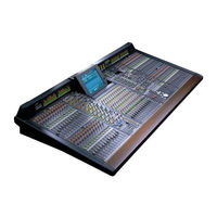
Yamaha PM1D Manager V2 Overview (1 page)
System Software V1.70
Brand:
Yamaha
| Category:
Software
| Size: 0.04 MB
Advertisement
Related Products
Yamaha PM-1000
Yamaha PM1200
Yamaha PM1800
Yamaha PM1800A
Yamaha RIVAGE PM10
Yamaha PM4000
Yamaha PM2800M
Yamaha PM3500M
Yamaha PM4000M
Yamaha PM-2000
Yamaha Categories
Motorcycle
Musical Instrument
Electronic Keyboard
Receiver
Amplifier
More Yamaha Manuals
Login
Sign In
OR
Sign in with Facebook
Sign in with Google
Upload manual
Upload from disk
Upload from URL