Sign In
Upload
Manuals
Brands
Yamaha Manuals
Recording Equipment
CS1D
Yamaha CS1D Manuals
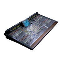
Manuals and User Guides for Yamaha CS1D. We have
3
Yamaha CS1D manuals available for free PDF download: Operating Manual, Owner's Manual, Service Manual
Yamaha CS1D Operating Manual (630 pages)
Digital Audio Mixing System Software V1.41
Brand:
Yamaha
| Category:
Recording Equipment
| Size: 26.84 MB
Table of Contents
Operating Manual (Start-Up)
20
Effect Parameters
3
Operating Notes
16
Table of Contents
20
About the "CS1D Operating Manual (Start-Up)
22
Introduction
22
Printing Conventions in "CS1D Operating Manual (Start-Up)
22
Introducing the Various Components
23
Terms Used in the "CS1D Operating Manual (Start-Up)
25
Connections (Standard Mode)
27
Connecting the Console and Engine (Standard Mode)
27
Connecting an Analog Input/Output Unit to the Engine
29
Mode)
30
Connecting a Digital Input/Output Unit to the Engine (Standard Mode)
30
Connections (Mirror Mode)
31
Connecting the Console and Engines (Mirror Mode)
31
Connecting an Analog Input/Output Unit to the Engines (Mirror Mode)
33
Connecting a Digital Input/Output Unit to the Engines (Mirror Mode)
34
Turning on the Power and Verifying the Connections
35
Turning on the Power
35
Checking the Status of each Device (Standard Mode)
36
Checking the Engine (Standard Mode)
36
Checking the Analog Input Unit (Standard Mode)
37
Checking the Analog Output Unit (Standard Mode)
38
Digital Input/Output Unit (Standard Mode)
38
Checking the Status of each Device (Mirror Mode)
39
Engines (Mirror Mode)
39
Checking the Analog Input Unit (Mirror Mode)
40
Checking the Analog Output Unit (Mirror Mode)
41
Checking the Digital Input/Output Unit (Mirror Mode)
42
Basic Settings (Standard Mode)
43
Selecting the Operation Mode (Standard Mode)
43
Setting the Word Clock (Standard Mode)
45
Basic Settings (Mirror Mode)
47
Selecting the Operation Mode (Mirror Mode)
47
Setting the Word Clock (Mirror Mode)
49
Checking the Operation of Input Units
51
Preparations for Checking
51
Connect the Monitor System
52
Connect an Input Source
53
Patch the Input Unit to an Input Channel
54
Monitor the Input Signal
57
Checking the Operation of an Output Unit
59
Preparations for Checking
59
Connect the Monitor System
60
Connect an Input Source
61
Patch the Input Unit to an Input Channel
62
Patch the STEREO a Channel to an Output Unit
63
Send the Input Signals of Input Channels 1/2 to the STEREO Bus
65
Turn off the Power
67
Operating Manual (Basic Operation)
69
Chapter 1. Introduction
73
About the "CS1D Operation Manual (Basic Operation)
73
Printing Conventions in the "CS1D Operation Manual (Basic Operation)
73
Component Structure
74
Full-Digital/Separate Type SR Mixing System
74
Overview of the PM1D System
74
Signal Flow in the PM1D System
76
Number of Inputs/Outputs and Channel Structure
78
MIX Buses/Matrix Buses
80
Scene Memories/Libraries
80
Word Clock Synchronization
80
Chapter 2. The User Interfaces of the CS1D
81
About the User Interfaces
81
User Interfaces Within the Display
81
User Interface on the Top Panel of the CS1D
83
External User Interfaces
84
Various Basic Operations
86
Click
86
Drag
86
Drag and Drop
87
Scroll
87
Accessing the Desired Screen
88
Button Operations
89
Moving the Cursor
90
Adjusting the Value of a Knob or Fader
91
Assigning a Name
92
Chapter 3. Audio Connections and Patching
94
Audio Connections
94
Audio Connections for an Analog Input Unit
94
Audio Connections for an Analog Output Unit
96
Audio Connections for a Digital Input/Output Unit
97
Audio Connections for the Console
98
Patching
100
Input Channel Patching
100
Output Channel Patching
102
Chapter 4. Basic Operation for Input Channels
104
About Input Channels
104
Blocks Used to Control Input Channels
104
Changing the Channel Assignments
105
Basic Operation INPUT Blocks/St in Block
106
INPUT Block/St in Block Controls and Functions
106
Head Amp Settings
108
Sending a Signal from an Input Channel to a STEREO Bus
110
Sending a Signal from an Input Channel to a MIX Bus
111
Pairing Settings
115
Basic Operation in the SELECTED INPUT CHANNEL Block
116
Controls and Functions of the SELECTED INPUT CHANNEL Block
116
Head Amp Settings
118
Sending Signals from an Input Channel to the STEREO Bus
119
Sending Signals from an Input Channel to a MIX Bus
121
Using the Delay
123
Using the Compressor
124
Using the Noise Gate
127
Using the 4 Band EQ/HPF
129
Chapter 5. Basic Operation for Output Channels
131
About the Output Channels
131
Blocks Used to Control the Output Channels
131
Switching the Channel Assignments
132
Basic Operation of the MIX OUTPUT Block
133
Controls and Functions of the MIX OUTPUT Block
133
Sending a Signal from a MIX Channel to an Output Unit
134
Sending a Signal from a MIX Channel to a MATRIX Bus
135
Sending a Signal from a MIX Channel to the STEREO Bus
137
Pairing MIX Channels
138
Basic Operation of the MATRIX OUTPUT Block
141
Controls and Functions of the MATRIX OUTPUT Block
141
Sending a Signal from a MATRIX Channel to an Output Unit
141
Pairing MATRIX Channels
142
Basic Operation of the STEREO OUTPUT Block
144
Controls and Functions of the STEREO OUTPUT Block
144
Sending a Signal from a STEREO A/B Channel to an Output Unit
145
Basic Operation of the SELECTED OUTPUT CHANNEL Block
146
Controls and Functions of the SELECTED OUTPUT CHANNEL Block
146
Sending a Signal from an Output Channel to an Output Unit
147
Sending a Signal from a MIX Channel to a MATRIX Bus/Stereo Bus
149
Sending a Signal from the STEREO a Channel to the MATRIX Bus
151
Delay Settings
152
Compressor Settings
153
Band EQ/HPF Settings
155
Chapter 6. Insert and Direct out
157
Insert
157
Connecting the External Device to be Inserted
157
Inserting into an Input Channel
158
Inserting into an Output Channel
161
Direct out
163
Direct out Connections
163
Directly Outputting an Input Channel Signal
163
Chapter 7. DCA Groups/Mute Groups
165
DCA Groups
165
Assigning a Channel to a DCA Group
165
Controlling a DCA Group
167
Mute Groups
168
Assigning Input Channels to a Mute Group
168
Assigning Output Channels to a Mute Group
169
Controlling a Mute Group
170
Chapter 8. Scene Memory
172
About Scenes
172
Scene Memory Operations
174
Storing a Scene
174
Recalling a Scene
175
Using PREVIEW Mode
176
Directly Recalling a Scene
177
Chapter 9. Recall Safe/Mute Safe
178
Recall Safe
178
Using the Console to Set/Defeat Recall Safe
178
Using the Screen to Set/Defeat Recall Safe
179
Mute Safe
180
Using the Console to Set/Defeat Mute Safe
180
Using the Screen to Set/Defeat Mute Safe
181
Chapter 10. Monitor
182
Basic Operation of the MONITOR A/MONITOR B Section
182
About MONITOR A/MONITOR B
182
Controls and Functions of the MONITOR A/MONITOR B Sections
183
Using the MONITOR a Section to Monitor a Signal
183
Using the MONITOR B Section to Monitor a Signal
185
Using the Cue/Solo Function
187
Cue Mode and solo Mode
187
Cue/Solo Groups
188
Controls and Functions of the CUE Section
189
Using the Cue Function
189
Using the solo Function
191
Chapter 11 . Talkback/Oscillator
192
Talkback
192
Oscillator
194
Chapter 12. Internal Effects
196
About the Internal Effects of the PM1D System
196
Patching an Internal Effect
197
Using an Internal Effect Via the MIX Bus
197
Inserting an Internal Effect into a Channel
200
Basic Operation of the Effect Screen
202
Editing Effect Parameters
202
Recalling Effect Data from the Library
203
Storing Effect Data to the Library
205
Chapter 13. Graphic EQ
206
Inserting a Graphic EQ into a Channel
206
Controlling a Graphic EQ
208
Controlling a Graphic EQ from the Display
208
Controlling a Graphic EQ from the DCA Faders
209
Chapter 14. MIDI/Time Code
211
Using MIDI Program Changes to Control Events
211
Using Time Code to Control Events
214
Chapter 15. Using a Memory Card to Save/Load Data
216
Saving a File Onto a Memory Card
216
Loading a File from a Memory Card
218
Chapter 16. Various Settings
220
Initial Settings for the Console
220
Setting the Internal Calendar and Clock
222
Specifying the Metering Points
223
Input Channel Metering Point
223
Output Channel Metering Point
224
User Defined Function Settings
225
Reference Manual (Hardware)
229
How the "CS1D Reference Manual (Hardware)" Is Organized
231
Printing Conventions in the "CS1D Reference Manual
233
INPUT Block
234
INPUT Block Channel Assignments
235
ST in Block
243
Channel Assignments for the ST in Block
243
SELECTED INPUT CHANNEL Block
249
48/Ø/Insert (+48/Phase/Insert) Section
251
INPUT Section
252
DELAY Section
252
MIX SEND Section
253
COMPRESSOR Section
255
NOISE GATE Section
257
EQUALIZER Section
259
STEREO Section
260
GAIN Section
261
ATTENUATOR Section
261
FADER Section
262
DCA Section
263
SAFE Section
264
CHANNEL SELECT Section
264
GLOBAL CONTROL Section
266
Display
269
MIX OUTPUT Block
270
Channel Assignments in the MIX OUTPUT Block
271
MIX Channel Section
272
MIX LAYER Section
275
MATRIX OUTPUT Block
276
MATRIX OUTPUT Block Channel Assignments
277
MATRIX Channel Section
278
MATRIX LAYER Section
281
STEREO OUTPUT Block
282
SELECTED OUTPUT CHANNEL Block
286
DELAY Section
289
COMPRESSOR Section
290
EQUALIZER Section
292
OUTPUT Section
293
DCA Section
295
SAFE Section
296
CHANNEL SELECT Section
296
DCA GROUP Block
299
Select the Items You Wish to Control from the DCA Faders
300
DCA Fader Section
301
FADER STATUS Section
303
MASTER Block
307
TALKBACK Section
308
OSCILLATOR Section
309
Card Slot Section
310
CUE Section
311
MONITOR a Section
313
MONITOR B Section
315
ENGINE Section
317
GLOBAL LAYER Section
317
METER Section
318
SCENE MEMORY Block
319
Scene Memory
320
LCD FUNCTION ACCESS/USER DEFINE Block
326
LCD ACCESS GLOBAL Section
327
LCD ACCESS OUTPUT Section
327
LCD ACCESS INPUT Section
328
User Define
328
Data Entry Block
329
Meter Bridge Block
331
Meter Section (Left)
332
Meter Section (Right)
332
TIME CODE Section
333
SCENE MEMORY Section
333
Rear Panel Block
334
DIGITAL I/O Section
335
2-TRACK in DIGITAL Section
336
STEREO out DIGITAL Section
336
WORD CLOCK Section
337
LAMP Connectors
337
2-TRACK in ANALOG Section
338
MONITOR out ANALOG Section
338
TALKBACK in 2 Section
339
CUE out ANALOG Section
339
DC POWER Section
340
CONTROL Section 1
341
CONTROL Section 2
342
Input/Output Signal Flow
343
Front Panel Block
344
Reference Manual (Software)
346
How the "CS1D Reference Manual (Software)" Is Organized
349
Printing Conventions in the "CS1D Reference Manual (Software)
349
Information Shown in the Display
350
Function Menu
354
Selecting a Function
354
Global Functions
357
EFFECT Functions
357
Using Internal Effects 1-8
357
Effect 1-Effect 8
357
Effect Assign
360
GEQ (Graphic EQ) Functions
361
Using the Internal 31 Band Graphic EQ on the Output Channels
361
Geq Parameter
361
GEQ ASSIGN 1-12/13-24 (Graphic EQ Assign 1-12/13-24)
364
SCENE Functions
366
Operating Scene Memories
366
Memory
366
Recall Safe
371
Fade Time
373
Direct Recall
375
MIDI/GPI/TC Function
377
Make MIDI/Gpi/Time Code -Related Settings
377
MIDI PROGRAM (MIDI Program Change)
377
TC EVENT (Time Code Event)
381
UTILITY Functions
384
Initial Settings for the PM1D System, and Loading/Saving Data or Libraries
384
Preference
384
User Define
386
Load/Save
388
SYS/W.CLOCK (System/Word Clock) Function
392
Make Settings Related to System/Word Clock
392
System Connection
392
Input Unit
395
Output Unit
398
Word Clock
401
Dither
404
METER Functions
406
Make Meter-Related Settings
406
Input Metering
406
Output Metering
408
MON/CUE (Monitor/Cue) Functions
410
Make Settings Related to Monitor and Cue
410
Talkback
410
Oscillator
412
2TR in (2 Track In)
415
ST out DIGITAL (Stereo out Digital)
416
Monitor a
417
Monitor B
420
Cue/Solo
422
Output Functions
424
OUT PATCH (Output Patch) Functions
424
Assign Output Units to Output Channels/Insert I/O
424
Output Patch
424
Insert Patch
426
Insert Point
428
Insert View
429
Name
431
OUT INSERT (Output Insert) Function
434
Settings for an Output Unit Inserted into an Output Channel
434
MIX 1-24 ins / MIX 25-48 ins / Matrix 1-24 ins / St Mas Ins/Unit Lib
434
OUT EQ (Output Equalizer) Function
437
Output Channel EQ Settings
437
Eq Parameter
437
MIX 1-24/MIX 25-48/Matrix 1-24/Stereo A, B
439
OUT COMP (Output Compressor) Function
441
Compressor Settings for Output Channels
441
COMP PRM (Compressor Parameters)
441
MIX 1-12 - MIX 37-48/Matrix 1-12 - Matrix 13-24/Stereo A, B
444
OUT DELAY (Output Delay) Function
447
Set the Channel-Independent Delay for Output Channels, and the Global Delay
447
MIX 1-24 /MIX 25-48/Matrix 1-24/Stereo A, B
447
OUT DCA/MUTE (Output Dca/Mute) Function
449
Set DCA and Mute Group Settings for the Output Channels
449
Dca Assign
449
Mute Group Assign
451
MATRIX/ST (Matrix/Stereo) Function
453
Send Signals from the MIX Channels, STEREO A/B Channels, and SUB in to the MATRIX Buses
453
MATRIX/ST ROUTING (Matrix/Stereo Routing)
453
MIX to MATRIX
456
Sub in
458
Lcr
460
OUT CH VIEW (Output Channel View) Function
462
View Output Channel Settings
462
CH VIEW (Channel View)
462
Input Functions
466
IN PATCH Functions
466
Assign Input/Output Units to Input Channels/Insert I/O/Direct out
466
Input Patch
466
Direct out Patch
468
Insert Patch
470
Insert/Direct Point
472
Insert/Direct View
474
Name
476
IN HA/INSERT (Input Head Amp/Insert) Functions
479
Settings for the Head Amp/Phase Section of the Input Unit
479
Ch 1-24 - Ch 73-96 / St in 1-8 / Ch 1-24 ins - Ch 73-96 ins / St in Ins/Unit Lib
479
IN EQ (Input Equalizer) Functions
482
Input Channel EQ Settings
482
Eq Parameter
482
Ch 1-24 - Ch 73-96/St in 1-8
485
IN GATE/COMP Function
487
Gate/Comp Settings for the Input Channel
487
GATE PRM (Gate Parameters)
487
COMP PRM (Compressor Parameters)
490
Ch 1-12 - Ch 85-96/St in 1-4 - St in 5-8
493
IN DELAY Functions
496
Make Settings for Individual Input Channel Delay
496
Ch 1-24 - Ch 72-96/St in 1-8
496
IN DCA/MUTE Functions
498
Set DCA, and Mute Group
498
Dca Assign
498
Mute Group Assign
500
PAN/ROUTING Function
502
CH to MIX (Channel to MIX)
502
Lcr
508
IN CH VIEW (Input Channel View) Function
510
View the Settings of an Input Channel
510
CH VIEW (Channel View)
510
Libraries
514
Basic Library Operation
514
Unit Library
518
Patch Library
520
Name Library
522
Input Eq Library
524
Output Eq Library
526
Input Gate Library
528
Input Comp Library
530
Output Comp Library
532
Input Channel Library
534
Output Channel Library
536
Effect Library
538
Geq Library
540
Other
542
Memory Initialization
542
Advertisement
Yamaha CS1D Owner's Manual (617 pages)
Control Surface Digital Audio Mixing System
Brand:
Yamaha
| Category:
Recording Equipment
| Size: 26.58 MB
Table of Contents
Operating Manual (Start-Up)
7
Operating Notes
3
Table of Contents
7
About the "CS1D Operating Manual (Start-Up)
9
Introduction
9
Printing Conventions in "CS1D Operating Manual (Start-Up)
9
Introducing the Various Components
10
Terms Used in the "CS1D Operating Manual (Start-Up)
12
Connections (Standard Mode)
14
Connecting the Console and Engine (Standard Mode)
14
Connecting an Analog Input/Output Unit to the Engine
16
Mode)
17
Connecting a Digital Input/Output Unit to the Engine (Standard Mode)
17
Connections (Mirror Mode)
18
Connecting the Console and Engines (Mirror Mode)
18
Connecting an Analog Input/Output Unit to the Engines (Mirror Mode)
20
Connecting a Digital Input/Output Unit to the Engines (Mirror Mode)
21
Turning on the Power and Verifying the Connections
22
Turning on the Power
22
Checking the Status of each Device (Standard Mode)
23
Checking the Engine (Standard Mode)
23
Checking the Analog Input Unit (Standard Mode)
24
Checking the Analog Output Unit (Standard Mode)
25
Digital Input/Output Unit (Standard Mode)
25
Checking the Status of each Device (Mirror Mode)
26
Engines (Mirror Mode)
26
Checking the Analog Input Unit (Mirror Mode)
27
Checking the Analog Output Unit (Mirror Mode)
28
Checking the Digital Input/Output Unit (Mirror Mode)
29
Basic Settings (Standard Mode)
30
Selecting the Operation Mode (Standard Mode)
30
Setting the Word Clock (Standard Mode)
32
Basic Settings (Mirror Mode)
34
Selecting the Operation Mode (Mirror Mode)
34
Setting the Word Clock (Mirror Mode)
36
Checking the Operation of Input Units
38
Preparations for Checking
38
Connect the Monitor System
39
Connect an Input Source
40
Patch the Input Unit to an Input Channel
41
Monitor the Input Signal
44
Checking the Operation of an Output Unit
46
Preparations for Checking
46
Connect the Monitor System
47
Connect an Input Source
48
Patch the Input Unit to an Input Channel
49
Patch the STEREO a Channel to an Output Unit
50
Send the Input Signals of Input Channels 1/2 to the STEREO Bus
52
Turn off the Power
54
Operating Manual (Basic Operation)
56
Chapter 1. Introduction
60
About the "CS1D Operation Manual (Basic Operation)
60
Printing Conventions in the "CS1D Operation Manual (Basic Operation)
60
Component Structure
61
Full-Digital/Separate Type SR Mixing System
61
Overview of the PM1D System
61
Signal Flow in the PM1D System
63
Number of Inputs/Outputs and Channel Structure
65
MIX Buses/Matrix Buses
67
Scene Memories/Libraries
67
Word Clock Synchronization
67
Chapter 2. The User Interfaces of the CS1D
68
About the User Interfaces
68
User Interfaces Within the Display
68
User Interface on the Top Panel of the CS1D
70
External User Interfaces
71
Various Basic Operations
73
Click
73
Drag
73
Drag and Drop
74
Scroll
74
Accessing the Desired Screen
75
Button Operations
76
Moving the Cursor
77
Adjusting the Value of a Knob or Fader
78
Assigning a Name
79
Chapter 3. Audio Connections and Patching
81
Audio Connections
81
Audio Connections for an Analog Input Unit
81
Audio Connections for an Analog Output Unit
83
Audio Connections for a Digital Input/Output Unit
84
Audio Connections for the Console
85
Patching
87
Input Channel Patching
87
Output Channel Patching
89
Chapter 4. Basic Operation for Input Channels
91
About Input Channels
91
Blocks Used to Control Input Channels
91
Changing the Channel Assignments
92
Basic Operation INPUT Blocks/St in Block
93
INPUT Block/St in Block Controls and Functions
93
Head Amp Settings
95
Sending a Signal from an Input Channel to a STEREO Bus
97
Sending a Signal from an Input Channel to a MIX Bus
98
Pairing Settings
102
Basic Operation in the SELECTED INPUT CHANNEL Block
103
Controls and Functions of the SELECTED INPUT CHANNEL Block
103
Head Amp Settings
105
Sending Signals from an Input Channel to the STEREO Bus
106
Sending Signals from an Input Channel to a MIX Bus
108
Using the Delay
110
Using the Compressor
111
Using the Noise Gate
114
Using the 4 Band EQ/HPF
116
Chapter 5. Basic Operation for Output Channels
118
About the Output Channels
118
Blocks Used to Control the Output Channels
118
Switching the Channel Assignments
119
Basic Operation of the MIX OUTPUT Block
120
Controls and Functions of the MIX OUTPUT Block
120
Sending a Signal from a MIX Channel to an Output Unit
121
Sending a Signal from a MIX Channel to a MATRIX Bus
122
Sending a Signal from a MIX Channel to the STEREO Bus
124
Pairing MIX Channels
125
Basic Operation of the MATRIX OUTPUT Block
128
Controls and Functions of the MATRIX OUTPUT Block
128
Sending a Signal from a MATRIX Channel to an Output Unit
128
Pairing MATRIX Channels
129
Basic Operation of the STEREO OUTPUT Block
131
Controls and Functions of the STEREO OUTPUT Block
131
Sending a Signal from a STEREO A/B Channel to an Output Unit
132
Basic Operation of the SELECTED OUTPUT CHANNEL Block
133
Controls and Functions of the SELECTED OUTPUT CHANNEL Block
133
Sending a Signal from an Output Channel to an Output Unit
134
Sending a Signal from a MIX Channel to a MATRIX Bus/Stereo Bus
136
Sending a Signal from the STEREO a Channel to the MATRIX Bus
138
Delay Settings
139
Compressor Settings
140
Band EQ/HPF Settings
142
Chapter 6. Insert and Direct out
144
Insert
144
Connecting the External Device to be Inserted
144
Inserting into an Input Channel
145
Inserting into an Output Channel
148
Direct out
150
Direct out Connections
150
Directly Outputting an Input Channel Signal
150
Chapter 7. DCA Groups/Mute Groups
152
DCA Groups
152
Assigning a Channel to a DCA Group
152
Controlling a DCA Group
154
Mute Groups
155
Assigning Input Channels to a Mute Group
155
Assigning Output Channels to a Mute Group
156
Controlling a Mute Group
157
Chapter 8. Scene Memory
159
About Scenes
159
Scene Memory Operations
161
Storing a Scene
161
Recalling a Scene
162
Using PREVIEW Mode
163
Directly Recalling a Scene
164
Chapter 9. Recall Safe/Mute Safe
165
Recall Safe
165
Using the Console to Set/Defeat Recall Safe
165
Using the Screen to Set/Defeat Recall Safe
166
Mute Safe
167
Using the Console to Set/Defeat Mute Safe
167
Using the Screen to Set/Defeat Mute Safe
168
Chapter 10. Monitor
169
Basic Operation of the MONITOR A/MONITOR B Section
169
About MONITOR A/MONITOR B
169
Controls and Functions of the MONITOR A/MONITOR B Sections
170
Using the MONITOR a Section to Monitor a Signal
170
Using the MONITOR B Section to Monitor a Signal
172
Using the Cue/Solo Function
174
Cue Mode and solo Mode
174
Cue/Solo Groups
175
Controls and Functions of the CUE Section
176
Using the Cue Function
176
Using the solo Function
178
Chapter 11 . Talkback/Oscillator
179
Talkback
179
Oscillator
181
Chapter 12. Internal Effects
183
About the Internal Effects of the PM1D System
183
Patching an Internal Effect
184
Using an Internal Effect Via the MIX Bus
184
Inserting an Internal Effect into a Channel
187
Basic Operation of the Effect Screen
189
Editing Effect Parameters
189
Recalling Effect Data from the Library
190
Storing Effect Data to the Library
192
Chapter 13. Graphic EQ
193
Inserting a Graphic EQ into a Channel
193
Controlling a Graphic EQ
195
Controlling a Graphic EQ from the Display
195
Controlling a Graphic EQ from the DCA Faders
196
Chapter 14. MIDI/Time Code
198
Using MIDI Program Changes to Control Events
198
Using Time Code to Control Events
201
Chapter 15. Using a Memory Card to Save/Load Data
203
Saving a File Onto a Memory Card
203
Loading a File from a Memory Card
205
Chapter 16. Various Settings
207
Initial Settings for the Console
207
Setting the Internal Calendar and Clock
209
Specifying the Metering Points
210
Input Channel Metering Point
210
Output Channel Metering Point
211
User Defined Function Settings
212
Reference Manual (Hardware)
216
How the "CS1D Reference Manual (Hardware)" Is Organized
218
Printing Conventions in the "CS1D Reference Manual
220
INPUT Block
221
INPUT Block Channel Assignments
222
Input Fader
227
ST in Block
230
Channel Assignments for the ST in Block
230
SELECTED INPUT CHANNEL Block
236
48/Ø/Insert (+48/Phase/Insert) Section
238
INPUT Section
239
DELAY Section
239
MIX SEND Section
240
COMPRESSOR Section
242
NOISE GATE Section
244
EQUALIZER Section
246
STEREO Section
247
GAIN Section
248
ATTENUATOR Section
248
FADER Section
249
DCA Section
250
SAFE Section
251
CHANNEL SELECT Section
251
GLOBAL CONTROL Section
253
Display
256
MIX OUTPUT Block
257
Channel Assignments in the MIX OUTPUT Block
258
MIX Channel Section
259
MIX LAYER Section
262
MATRIX OUTPUT Block
263
MATRIX OUTPUT Block Channel Assignments
264
MATRIX Channel Section
265
MATRIX LAYER Section
268
STEREO OUTPUT Block
269
SELECTED OUTPUT CHANNEL Block
273
DELAY Section
276
COMPRESSOR Section
277
EQUALIZER Section
279
OUTPUT Section
280
DCA Section
282
SAFE Section
283
CHANNEL SELECT Section
283
DCA GROUP Block
286
Select the Items You Wish to Control from the DCA Faders
287
DCA Fader Section
288
FADER STATUS Section
290
MASTER Block
294
TALKBACK Section
295
OSCILLATOR Section
296
Card Slot Section
297
CUE Section
298
MONITOR a Section
300
MONITOR B Section
302
ENGINE Section
304
GLOBAL LAYER Section
304
METER Section
305
SCENE MEMORY Block
306
Scene Memory
307
LCD FUNCTION ACCESS/USER DEFINE Block
313
LCD ACCESS GLOBAL Section
314
LCD ACCESS OUTPUT Section
314
LCD ACCESS INPUT Section
315
User Define
315
Data Entry Block
316
Meter Bridge Block
318
Meter Section (Left)
319
Meter Section (Right)
319
TIME CODE Section
320
SCENE MEMORY Section
320
Rear Panel Block
321
DIGITAL I/O Section
322
2-TRACK in DIGITAL Section
323
STEREO out DIGITAL Section
323
WORD CLOCK Section
324
LAMP Connectors
324
2-TRACK in ANALOG Section
325
MONITOR out ANALOG Section
325
TALKBACK in 2 Section
326
CUE out ANALOG Section
326
DC POWER Section
327
CONTROL Section 1
328
CONTROL Section 2
329
Input/Output Signal Flow
330
Front Panel Block
331
Reference Manual (Software)
333
How the "CS1D Reference Manual (Software)" Is Organized
336
Printing Conventions in the "CS1D Reference Manual (Software)
336
Information Shown in the Display
337
Function Menu
341
Selecting a Function
341
Global Functions
344
EFFECT Functions
344
Using Internal Effects 1-8
344
Effect 1-Effect 8
344
Effect Assign
347
GEQ (Graphic EQ) Functions
348
Using the Internal 31 Band Graphic EQ on the Output Channels
348
Geq Parameter
348
GEQ ASSIGN 1-12/13-24 (Graphic EQ Assign 1-12/13-24)
351
SCENE Functions
353
Operating Scene Memories
353
Memory
353
Recall Safe
358
Fade Time
360
Direct Recall
362
MIDI/GPI/TC Function
364
Make MIDI/Gpi/Time Code -Related Settings
364
MIDI PROGRAM (MIDI Program Change)
364
TC EVENT (Time Code Event)
368
UTILITY Functions
371
Initial Settings for the PM1D System, and Loading/Saving Data or Libraries
371
Preference
371
User Define
373
Load/Save
375
SYS/W.CLOCK (System/Word Clock) Function
379
Make Settings Related to System/Word Clock
379
System Connection
379
Input Unit
382
Output Unit
385
Word Clock
388
Dither
391
METER Functions
393
Make Meter-Related Settings
393
Input Metering
393
Output Metering
395
MON/CUE (Monitor/Cue) Functions
397
Make Settings Related to Monitor and Cue
397
Talkback
397
Oscillator
399
2TR in (2 Track In)
402
ST out DIGITAL (Stereo out Digital)
403
Monitor a
404
Monitor B
407
Cue/Solo
409
Output Functions
411
OUT PATCH (Output Patch) Functions
411
Assign Output Units to Output Channels/Insert I/O
411
Output Patch
411
Insert Patch
413
Insert Point
415
Insert View
416
Name
418
OUT INSERT (Output Insert) Function
421
Settings for an Output Unit Inserted into an Output Channel
421
MIX 1-24 ins / MIX 25-48 ins / Matrix 1-24 ins / St Mas Ins/Unit Lib
421
OUT EQ (Output Equalizer) Function
424
Output Channel EQ Settings
424
Eq Parameter
424
MIX 1-24/MIX 25-48/Matrix 1-24/Stereo A, B
426
OUT COMP (Output Compressor) Function
428
Compressor Settings for Output Channels
428
COMP PRM (Compressor Parameters)
428
MIX 1-12 - MIX 37-48/Matrix 1-12 - Matrix 13-24/Stereo A, B
431
OUT DELAY (Output Delay) Function
434
Set the Channel-Independent Delay for Output Channels, and the Global Delay
434
MIX 1-24 /MIX 25-48/Matrix 1-24/Stereo A, B
434
OUT DCA/MUTE (Output Dca/Mute) Function
436
Set DCA and Mute Group Settings for the Output Channels
436
Dca Assign
436
Mute Group Assign
438
MATRIX/ST (Matrix/Stereo) Function
440
Send Signals from the MIX Channels, STEREO A/B Channels, and SUB in to the MATRIX Buses
440
MATRIX/ST ROUTING (Matrix/Stereo Routing)
440
MIX to MATRIX
443
Sub in
445
Lcr
447
Screen Functions
447
OUT CH VIEW (Output Channel View) Function
449
View Output Channel Settings
449
CH VIEW (Channel View)
449
Input Functions
453
IN PATCH Functions
453
Assign Input/Output Units to Input Channels/Insert I/O/Direct out
453
Input Patch
453
Direct out Patch
455
Insert Patch
457
Insert/Direct Point
459
Insert/Direct View
461
Name
463
IN HA/INSERT (Input Head Amp/Insert) Functions
466
Settings for the Head Amp/Phase Section of the Input Unit
466
Ch 1-24 - Ch 73-96 / St in 1-8 / Ch 1-24 ins - Ch 73-96 ins / St in Ins/Unit Lib
466
IN EQ (Input Equalizer) Functions
469
Input Channel EQ Settings
469
Eq Parameter
469
Ch 1-24 - Ch 73-96/St in 1-8
472
IN GATE/COMP Function
474
Gate/Comp Settings for the Input Channel
474
GATE PRM (Gate Parameters)
474
COMP PRM (Compressor Parameters)
477
Ch 1-12 - Ch 85-96/St in 1-4 - St in 5-8
480
IN DELAY Functions
483
Make Settings for Individual Input Channel Delay
483
Ch 1-24 - Ch 72-96/St in 1-8
483
IN DCA/MUTE Functions
485
Set DCA, and Mute Group
485
Dca Assign
485
Mute Group Assign
487
PAN/ROUTING Function
489
CH to MIX (Channel to MIX)
489
Lcr
495
IN CH VIEW (Input Channel View) Function
497
View the Settings of an Input Channel
497
CH VIEW (Channel View)
497
Libraries
501
Basic Library Operation
501
Unit Library
505
Patch Library
507
Name Library
509
Input Eq Library
511
Output Eq Library
513
Input Gate Library
515
Input Comp Library
517
Output Comp Library
519
Input Channel Library
521
Output Channel Library
523
Effect Library
525
Geq Library
527
Other
529
Memory Initialization
529
Yamaha CS1D Service Manual (150 pages)
Brand:
Yamaha
| Category:
Music Mixer
| Size: 12.23 MB
Table of Contents
Table of Contents
1
Control Surface
1
Specifications
5
Panel Layout
7
Connector Circuit Diagram
8
Circuit Boards
17
Disassembly Procedure
20
Circuit Board
27
Power Supply Unit
32
Lsi Pin Description
36
IC Block Diagram
44
Mtcpu
49
Circuit Boards
50
Mtcpu
52
Mb22
58
Cnds1,Lampvr,Lcdc
59
Pcif
63
Pcif
65
Pnis3,Pnm3
66
Ccas
71
Pnc1
72
Cutbvl2,Hmvola2,Hmvolb2
74
Pnm1
78
Pnm1
79
Pnos4
81
Mscpu
82
Pnos3,Pnos6
86
Pnos1R
87
Pnos1L
88
Pnos1C
89
Iscpu
92
Oscpu
93
Pnis1
94
Pnis1
96
Pnis2
97
Pnis2
98
Incpu
100
Pni1
102
Pni1
103
Inspection
104
Inspection
107
Test Program
108
Test Program
110
Block Diagram
135
Advertisement
Advertisement
Related Products
Yamaha CS6X
Yamaha CS6R
Yamaha CRW2216E-NB
Yamaha CDR200t
Yamaha CDR400At
Yamaha CRW4261t-NB
Yamaha CRW4261t
Yamaha CBX-T3
Yamaha CDR-HD1300
Yamaha CRD-HD1300
Yamaha Categories
Motorcycle
Musical Instrument
Electronic Keyboard
Receiver
Amplifier
More Yamaha Manuals
Login
Sign In
OR
Sign in with Facebook
Sign in with Google
Upload manual
Upload from disk
Upload from URL