Sign In
Upload
Manuals
Brands
Toshiba Manuals
Laptop
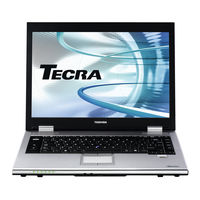
TECRA P5
Toshiba TECRA P5 Manuals
Manuals and User Guides for Toshiba TECRA P5. We have
4
Toshiba TECRA P5 manuals available for free PDF download: Maintenace Manual, Maintenance Manual, User Manual
Toshiba TECRA P5 Maintenace Manual (406 pages)
Toshiba TECRA A9 Series; TECRA S5; TECRA P5; Satellite Pro S200 Notebook
Brand:
Toshiba
| Category:
Laptop
| Size: 14.57 MB
Table of Contents
Troubleshooting Procedures
7
Chapter 4 Replacement Procedures
3
General
3
Table of Contents
7
Hardware Overview
12
Table of Contents
14
Chapter 1 Contents
16
Features
16
Figure 1-1 Front of the Computer
21
Figure 1-2 System Unit Configuration
22
Figure 1-3 System Unit Block Diagram
23
Figure 1-4 3.5-Inch FDD (USB External)
29
Table 1-1 3.5-Inch FDD Specifications
29
Inch Floppy Disk Drive (Usb External)
29
Figure 1-5 2.5-Inch HDD
30
Table 1-2 2.5-Inch HDD Specifications
30
Inch Hard Disk Drive
30
Optical Drive (Odd)
31
DVD Super Multi Drive Specifications
33
Keyboard
34
TFT Color Display
35
Figure 1-7 LCD Module
35
Table 1-4 LCD Module Specifications
35
FL Inverter Board Specifications
36
Power Supply
37
Table 1-6 Power Supply Output Rating
38
Table 1-7 Battery Specifications
42
Batteries
42
Main Battery
42
Table 1-8 Time Required for Charges
43
Fluorescent Lamp
43
Battery Charging Control
43
Table 1-9 RTC Battery Charging/Data Preservation Time
44
Table 1-10 AC Adapter Specifications
45
Chapter 2 Troubleshooting Procedures
46
Troubleshooting
51
Troubleshooting Flowchart
53
Power Supply Troubleshooting
57
Procedure 3 Connection Check
64
Procedure 5 Replacement Check
66
System Board Troubleshooting
67
Procedure 4 Replacement Check
81
USB FDD Troubleshooting
82
HDD Troubleshooting
85
Procedure 2 Partition Check
86
Procedure 4 Diagnostic Test Program Execution Check
88
Keyboard and Dual Point Troubleshooting
90
Display Troubleshooting
92
Optical Drive Troubleshooting
94
Modem Troubleshooting
96
LAN Troubleshooting
98
Bluetooth Troubleshooting
99
Procedure 2 Connection Check
100
Procedure 3 Replacement Check
101
Wireless LAN Troubleshooting
102
Sound Troubleshooting
105
Procedure 2 Connector Check
106
Bridge Media Slot Troubleshooting
108
Fingerprint Sensor Troubleshooting
109
Smartcard Slot Troubleshooting (Smartcard Model Only)
119
Chapter 3 Tests and Diagnostics
120
Table of Contents
122
The Diagnostic Test
126
Diagnostics Menu
126
H/W (Hardware) Initial Information Setting Tool
129
Heatrun Test Program
129
Executing the Diagnostic Test
130
Repair Main
130
Diagnostics Menu (T&D)
131
Version X.XX (C) Copyright Toshiba Corp. 20Xx
132
Repair Initial Config Set
134
H/W Initial Information Setting Tool
134
Heatrun Test Program
134
Setting of the Hardware Configuration
135
Heatrun Test
137
Subtest Names
138
System Test
140
Memory Test
142
Keyboard Test
143
Display Test
144
Floppy Disk Test
147
Printer Test
149
Async Test
151
Hard Disk Test
152
Real Timer Test
155
NDP Test
157
Expansion Test
158
CD-ROM/DVD-ROM Test
160
Error Code and Error Status Names
161
Hard Disk Test Detail Status
164
Only One Test
166
Subtest 1 Pressed Key Display
167
Subtest 2 Touch Pad
168
Subtest 3 Wireless Communication Switch
169
Subtest 4 USB Port Select Menu
169
Subtest 5 LED
170
Subtest 6 Buuton
170
Subtest 7 Acceleration Sensor
171
Subtest 8 Docker Dock/Undock
173
Subtest 9 Fan Control
174
Subtest a Smart Card
174
Head Cleaning
175
Function Description
175
Operations
175
Log Utilities
176
Function Description
176
Operations
177
Running Test
178
Function Description
178
Operations
178
Floppy Disk Drive Utilities
179
Function Description
179
Operations
180
Fdd Utilities
180
System Configuration
184
Function Description
184
Operations
185
Wireless LAN Test Program (Intel-Made B/G, A/B/G Setting up of REF PC)
186
Wireless LAN Test Program on DUT PC(Intel-Made)
191
Wireless LAN Test Program (Intel-Made :Golan) on DUT PC
191
Wireless LAN Test Program (Intel-Made:kedron) on DUT PC
195
Lan/Modem/Bluetooth/Ieee1394 Test Program
199
LAN Test
199
Modem Test
202
Bluetooth Test
203
IEEE1394 Test
205
Sound Test Program
206
Bios Setup
207
Replacement Procedures
226
Table of Contents
228
Safety Precautions
233
Disassembly Procedure
235
Assembly Procedures
236
Screw Tightening Torque
237
Screw Notation
238
Battery Pack
239
Removing the Battery Pack
239
PC Card
241
Bridge Media
242
Removing the Bridge Media
242
Smartcard
243
Hdd
244
MDC/Memory Module
248
Keyboard
251
Installing the Keyboard
254
Bluetooth Module
255
Removing the Bluetooth Module
255
Installing the Bluetooth Module
256
SW Membrane
257
Fan Hood
259
Removing the Fan Hood
259
Removing the Wireless Lan Card
261
Wireless LAN Card
261
Optical Drive
265
Removing the Optical Drive
265
Installing the Optical Drive
267
Removing the Touch Pad
268
Touch Pad
268
Cover Assembly and Base Assembly
271
Removing the Cover Assembly and Base Assembly
271
Fingerprint Sensor Board
274
Removing the Fingerprint Sensor Board
274
RTC Battery
277
Removing the Rtc Battery
278
Microphone
279
Installing the Microphone
280
Removing the Rgb Board
281
RGB Board
281
Removing the System Board
284
System Board
284
Smartcard Unit
291
Battery Lock/Battery Latch
293
Removing the Battery Lock/Battery Latch
293
HDD Cable/Lan Jack/Rgb Board Cable
295
Removing the Hdd Cable/Lan Jack/Rgb Board Cable
295
North Bridge (and GPU) Heat Sink/Cpu Heat Sink/Fan/Cpu
297
PC Card Slot
305
LCD Unit/Fl Inverter
306
Cover Latch
310
Removing the Cover Latch
310
Removing the Wireless Lan Antenna/Bluetooth Antenna
311
Wireless LAN Antenna/Bluetooth Antenna
311
LCD Cable
322
Removing the Lcd Cable
322
Hinge
324
Removing the Speaker
327
Speaker
327
Installing the Speaker
329
Fluorescent Lamp
330
Replacing the 15.4-Inch Wxga Samsung Fluorescent Lamp
331
Replacing the 15.4-Inch Wsxga+ Samsung Fluorescent Lamp
335
Appendix
342
Handling the LCD Module
342
Keyboard Scan/Character Codes
343
BIOS Rewrite Procedures
344
Appendix A Handling the LCD Module
348
Appendix Contents
348
Appendix B Board Layout
354
System Board (FHMLS*) Front View
354
System Board (FHMLS *) Back View
356
Serial & RGB Board (FHMLR*) Front View
358
Fingerprint Sensor Board (FHMLF*) Front and Back View
359
Appendix C Pin Assignments
360
CN1400 SO-DIMM0 Connector (200-Pin
360
System Board (FHMLS*)
360
CN1410 SO-DIMM1 Connector (200-Pin
363
CN1810 ODD Interface Connector (50-Pin
366
CN1900 HDD(SATA) Interface Connector (11-Pin
367
CN2110 PC Card Interface Connector (70-Pin
368
IS2150 Bridge Media Interface Connector (46-Pin
369
CN2300 Docking Interface Connector (133-Pin
370
CN2650 Mini PCI Express I/F Connector(Robson) (52-Pin
374
CN3010 MDC Interface Connector (12-Pin
375
CN3230 Keyboard Interface Connector (34-Pin
375
CN3240 Dual Point Interface Connector (8-Pin
376
CN3490 Debug Port Interface Connector (8-Pin
376
CN4100 LAN Interface Connector (14-Pin
376
CN4230 IEEE 1394 Interface Connector (4-Pin
377
CN4400 Bluetooth1 Interface Connector (20-Pin
377
CN4440 Bluetooth2 Interface Connector (20-Pin
378
CN4610 USB Port 4 Connector (8-Pin
378
CN4612 USB Port 6 Connector (8-Pin
378
CN5000 LCD Interface Connector (40-Pin
379
CN6050 Internal Microphone Connector (2-Pin
380
CN6170 Speaker Connector (4-Pin
380
J6051 External Microphone Connector (6-Pin
380
CN8771 FAN Interface Connector (4-Pin
381
CN8800 DC-IN Connector (4-Pin
381
CN8810 Main Battery Connector (10-Pin
381
J6310 Headphone Connector (6-Pin
381
CN9300 RTC Battery Connector (3-Pin
382
CN9540 Web Camera Interface Connector (3-Pin
383
CN9550 Fingerprint Sensor Board Interface Connector (8-Pin
383
CN9721 Switch Interface Connector (13-Pin
383
CN2170 Smart Card Interface Connector (10-Pin
384
CN5080 RGB Interface Connector (15-Pin
385
CN9600 System Board(Fhmls*)Interface Connector (40-Pin
385
Serial & RGB Board (FHMLR*)
385
CN9601 Serial Interface Connector (9-Pin
386
CN9650 System Board(FHMLS*) Interface Connector (8-Pin
386
Fingerprint Sensor Board (FHMLF*)
386
Appendix D Keyboard Scan/Character Codes
387
Appendix E Key Layout
395
United Kingdom (UK) Keyboard
395
United States (US) Keyboard
395
Appendix F Wiring Diagrams
397
RGB Monitor Loopback Connector
397
RS-232C Loopback Connector
397
RS-232C Direct Connection Cable (9-Pin to 25-Pin
398
RS-232C Direct Connection Cable (9-Pin to 9-Pin
398
LAN Loopback Connector
399
Advertisement
Toshiba TECRA P5 Maintenance Manual (405 pages)
Brand:
Toshiba
| Category:
Laptop
| Size: 13.97 MB
Table of Contents
Table of Contents
6
Hardware Overview
11
Table of Contents
13
Features
15
Figure 1-1 Front of the Computer
20
Figure 1-2 System Unit Configuration
21
Figure 1-3 System Unit Block Diagram
22
Figure 1-4 3.5-Inch FDD (USB External)
28
Inch Floppy Disk Drive (Usb External)
28
Table 1-1 3.5-Inch FDD Specifications
28
Figure 1-5 2.5-Inch HDD
29
Inch Hard Disk Drive
29
Table 1-2 2.5-Inch HDD Specifications
29
Optical Drive (Odd)
30
DVD Super Multi Drive Specifications
32
Keyboard
33
Figure 1-7 LCD Module
34
Table 1-4 LCD Module Specifications
34
TFT Color Display
34
FL Inverter Board Specifications
35
Power Supply
36
Table 1-6 Power Supply Output Rating
37
AC Adaptor
41
Main Battery
41
Table 1-8 Time Required for Charges
42
Battery Charging Control
42
Table 1-9 RTC Battery Charging/Data Preservation Time
43
Table 1-10 AC Adapter Specifications
44
Batteries
41
Table 1-7 Battery Specifications
41
Chapter 1 Hardware Overview
46
Chapter 2 Troubleshooting Procedures
46
Troubleshooting
52
Troubleshooting Flowchart
53
Power Supply Troubleshooting
57
Procedure 3 Connection Check
64
Procedure 5 Replacement Check
66
System Board Troubleshooting
67
Procedure 4 Replacement Check
81
USB FDD Troubleshooting
82
HDD Troubleshooting
85
Procedure 2 Partition Check
86
Procedure 4 Diagnostic Test Program Execution Check
88
Keyboard and Dual Point Troubleshooting
90
Display Troubleshooting
93
Optical Drive Troubleshooting
95
Modem Troubleshooting
97
LAN Troubleshooting
99
Bluetooth Troubleshooting
100
Procedure 2 Connection Check
101
Procedure 3 Replacement Check
102
Wireless LAN Troubleshooting
103
Sound Troubleshooting
106
Procedure 2 Connector Check
107
Bridge Media Slot Troubleshooting
109
Fingerprint Sensor Troubleshooting
110
Chapter 3 Tests and Diagnostics
120
Table of Contents
122
The Diagnostic Test
126
Diagnostics Menu
126
H/W (Hardware) Initial Information Setting Tool
128
Heatrun Test Program
128
Executing the Diagnostic Test
129
Diagnostics Menu (T&D)
130
Repair Initial Config Set
133
H/W Initial Information Setting Tool
133
Heatrun Test Program
133
Setting of the Hardware Configuration
134
Heatrun Test
136
Subtest Names
137
System Test
139
Memory Test
141
Keyboard Test
142
Display Test
143
Floppy Disk Test
146
Printer Test
148
Async Test
150
Hard Disk Test
151
Real Timer Test
154
NDP Test
156
Expansion Test
157
CD-ROM/DVD-ROM Test
159
Error Code and Error Status Names
160
Hard Disk Test Detail Status
163
Only One Test
165
Program Description
165
Operations
165
Head Cleaning
174
Function Description
174
Operations
174
Log Utilities
175
Function Description
175
Operations
176
Running Test
177
Function Description
177
Operations
177
Floppy Disk Drive Utilities
178
Function Description
178
Operations
179
System Configuration
183
Function Description
183
Operations
184
Wireless LAN Test Program (Intel-Made B/G, A/B/G Setting up of REF PC)
185
Wireless LAN Test Program on DUT PC(Intel-Made)
190
Lan/Modem/Bluetooth/Ieee1394 Test Program
198
LAN Test
198
Modem Test
201
Bluetooth Test
202
IEEE1394 Test
204
Sound Test Program
205
Sound (Standard) Test
205
Sound (Legacy) Test
207
CD Sound (Standard) Test
208
CD Sound (Legacy) Test
210
Bios Setup
211
Replacement Procedures
230
Table of Contents
232
Safety Precautions
237
Disassembly Procedure
239
Assembly Procedures
240
Screw Tightening Torque
241
Screw Notation
242
Chapter 4 Contents
243
Battery Pack
243
PC Card
245
Bridge Media
246
Hdd
247
MDC/Memory Module
251
Keyboard
254
Removing the Keyboard
254
Installing the Keyboard
257
Bluetooth Module
258
Installing the Bluetooth Module
259
SW Membrane
260
Fan Hood
262
Wireless LAN Card
264
Optical Drive
268
Installing the Optical Drive
270
Cover Assembly and Base Assembly
271
Removing the Cover Assembly and Base Assembly
271
Removing the Touch Pad
274
Touch Pad
275
Fingerprint Sensor Board
277
RTC Battery
280
Removing the Rtc Battery
281
Installing the Microphone
282
Microphone
282
Removing the Microphone
282
RGB Board
283
System Board
286
Battery Lock/Battery Latch
293
HDD Cable/Lan Jack/Rgb Board Cable
295
Removing the Hdd Cable/Lan Jack/Rgb Board Cable
295
North Bridge (and GPU) Heat Sink/Cpu Heat Sink/Fan/Cpu
297
PC Card Slot
305
LCD Unit/Fl Inverter
306
Cover Latch
310
Removing the Wireless Lan Antenna/Bluetooth Antenna
311
Wireless LAN Antenna/Bluetooth Antenna
311
LCD Cable
322
Hinge
324
Removing the Hinge
324
Removing the Speaker
327
Speaker
327
Installing the Speaker
329
Fluorescent Lamp
330
Replacing the 15.4-Inch Wxga Samsung Fluorescent Lamp
331
Replacing the 15.4-Inch Wsxga+ Samsung Fluorescent Lamp
335
Appendix
342
Appendix A Handling the LCD Module
348
Appendix Contents
348
Appendix B Board Layout
354
System Board (FHMLS*) Front View
354
System Board (FHMLS *) Back View
356
Serial & RGB Board (FHMLR*) Front View
358
Fingerprint Sensor Board (FHMLF*) Front and Back View
359
Appendix C Pin Assignments
360
CN1400 SO-DIMM0 Connector (200-Pin
360
System Board (FHMLS*)
360
CN1410 SO-DIMM1 Connector (200-Pin
363
CN1810 ODD Interface Connector (50-Pin
366
CN1900 HDD(SATA) Interface Connector (11-Pin
367
CN2110 PC Card Interface Connector (70-Pin
368
IS2150 Bridge Media Interface Connector (46-Pin
369
CN2300 Docking Interface Connector (133-Pin
370
CN2650 Mini PCI Express I/F Connector(Robson) (52-Pin
374
CN3010 MDC Interface Connector (12-Pin
375
CN3230 Keyboard Interface Connector (34-Pin
375
CN3240 Dual Point Interface Connector (8-Pin
376
CN3490 Debug Port Interface Connector (8-Pin
376
CN4100 LAN Interface Connector (14-Pin
376
CN4230 IEEE 1394 Interface Connector (4-Pin
377
CN4400 Bluetooth1 Interface Connector (20-Pin
377
CN4440 Bluetooth2 Interface Connector (20-Pin
378
CN4610 USB Port 4 Connector (8-Pin
378
CN4612 USB Port 6 Connector (8-Pin
378
CN5000 LCD Interface Connector (40-Pin
379
CN6050 Internal Microphone Connector (2-Pin
380
CN6170 Speaker Connector (4-Pin
380
J6051 External Microphone Connector (6-Pin
380
CN8771 FAN Interface Connector (4-Pin
381
CN8800 DC-IN Connector (4-Pin
381
CN8810 Main Battery Connector (10-Pin
381
J6310 Headphone Connector (6-Pin
381
CN9300 RTC Battery Connector (3-Pin
382
CN9540 Web Camera Interface Connector (3-Pin
383
CN9550 Fingerprint Sensor Board Interface Connector (8-Pin
383
CN9721 Switch Interface Connector (13-Pin
383
CN5080 RGB Interface Connector (15-Pin
384
CN9600 System Board(Fhmls*)Interface Connector (40-Pin
384
Serial & RGB Board (FHMLR*)
384
CN9601 Serial Interface Connector (9-Pin
385
CN9650 System Board(FHMLS*) Interface Connector (8-Pin
385
Fingerprint Sensor Board (FHMLF*)
385
Appendix D Keyboard Scan/Character Codes
386
Appendix E Key Layout
394
United Kingdom (UK) Keyboard
394
United States (US) Keyboard
394
Appendix F Wiring Diagrams
396
RGB Monitor Loopback Connector
396
RS-232C Loopback Connector
396
RS-232C Direct Connection Cable (9-Pin to 25-Pin
397
RS-232C Direct Connection Cable (9-Pin to 9-Pin
397
LAN Loopback Connector
398
Appendix G BIOS Rewrite Procedures
400
Toshiba TECRA P5 User Manual (242 pages)
Brand:
Toshiba
| Category:
Laptop
| Size: 11.15 MB
Table of Contents
User's Manual
2
Table of Contents
2
Copyright
6
Disclaimer
6
Trademarks
6
Fcc Conditions
7
FCC Information
7
EU Declaration of Conformity
8
How to Confirm Modem Module Label
8
Modem Warning Notice
8
VCCI Class B Information
8
Japan Regulations
9
Region Selection
9
If Problems Arise
10
Telephone Company Procedures
10
Type of Service
10
Fax Branding
11
Instructions for IC CS-03 Certified Equipment
11
Notes for Users in Australia and New Zealand
12
General Conditions
14
Following Information Is Only for EU-Member States
15
Optical Disc Drive Safety Instructions
16
International Precautions
21
Conventions
23
Preface
23
Creating a Computer-Friendly Environment
26
General Precautions
26
Stress Injury
26
Heat Injury
27
Instruction Manual for Safety and Comfort
27
Mobile Phones
27
PC Card Overheating
27
Pressure or Impact Damage
27
Chapter 1 Getting Started
28
Equipment Checklist
28
Getting Started
28
Getting Started
30
Connecting the Ac Adaptor
31
Opening the Display
33
Shut down Mode (Boot Mode)
34
Starting up for the First Time
34
Turning off the Power
34
Sleep Mode
35
Hibernation Mode
37
Turning on the Power
34
Restarting the Computer
38
System Recovery Options
39
System Recovery
40
Chapter 2 The Grand Tour
43
Front with the Display Closed
43
Left Side
45
Downloaded from Lpmanual.com Manuals User's Manual
45
Right Side
46
Back
47
Underside
49
Front with the Display Open
50
Indicators
53
System Indicators
53
Keyboard Indicators
54
Optical Disc Drives
55
Region Codes for DVD Drives and Media
55
Writable Discs
55
DVD Super Multi Drive Double Layer
56
AC Adaptor
57
Chapter 3 Hardware, Utilities and Options
59
Hardware
59
Optical Disc Drive
61
Special Features
63
TOSHIBA Value Added Package
66
Utilities and Applications
68
Optional Devices
71
Inserting a Pc Card
71
Peripheral Devices
71
Removing a Pc Card
72
Bridge Media Slot
73
Memory Card Care
74
Inserting Memory Media
75
Removing Memory Media
76
Additional Memory Module
77
Battery Charger
81
External Monitor
81
Usb Fdd Kit
82
Serial Port
86
Toshiba Express Port Replicator
86
Security Lock
87
Connecting the Security Lock
87
Optional Accessories
88
Chapter 4 Operating Basics
89
TOSHIBA Dual Pointing Device
89
Accupoint Precautions
90
Using the Accupoint
90
Replacing the Cap
91
Using the Fingerprint Sensor
91
Points to Note about the Fingerprint Sensor
92
How to Delete the Fingerprint Data
94
Fingerprint Registration
95
Windows Logon Via Fingerprint Authentication
96
How to Enable Fingerprint Power-On Security Settings
97
Fingerprint Utility Limitations
98
Using Optical Disc Drives
98
Loading Discs
99
Removing Discs
100
Writing Cds on DVD-ROM&CD-R/RW Drive
102
Before Writing or Rewriting
102
When Writing or Rewriting
103
Writing CD/Dvds on DVD Super Multi Drives
104
Important Message
104
Toshiba Disc Creator
108
Data Verification
109
How to Learn more about Toshiba Disc Creator
109
Media Care
110
Floppy Diskettes
110
Sound System
111
Microphone Level
111
Power Management
112
Modem
113
Toshiba MIC Effect
113
Properties Menu
114
Dialing Properties
115
Modem Selection
115
Wireless Communications
117
Wireless Lan
117
Worldwide Operation
118
Product Support
119
Radio Links
119
Wireless Communication Switch
119
Lan
120
Wireless Communication Indicator
120
Connecting the Lan Cable
121
Disconnecting the Lan Cable
122
Computer Handling
122
Cleaning the Computer
122
Moving the Computer
122
Using the Hard Disk Drive (HDD) Protection
123
Taskbar Icon
123
Hdd Protection
124
Toshiba Hdd Protection Properties
124
Heat Dispersal
125
Chapter 5 The Keyboard
126
Typewriter Keys
126
Function Keys: F1
127
Soft Keys: FN Key Combinations
127
Hot Keys
128
Windows Special Keys
130
Keypad Overlay
130
Arrow Mode
131
Numeric Mode
131
Temporarily Changing Modes
132
Generating ASCII Characters
132
Chapter 6 Power and Power-Up Modes
133
Power Conditions
133
Monitoring of Power Condition
134
Battery Indicator
134
Battery
135
Battery Pack
135
Battery Types
135
DC in Indicator
135
Power Indicator
135
Charging the Batteries
137
Battery Charging Notice
138
Monitoring Battery Capacity
138
Extending Battery Life
139
Maximizing Battery Operating Time
139
Removing the Battery Pack
140
Replacing the Battery Pack
140
Installing the Battery Pack
141
TOSHIBA Password Utility
142
User Password
142
Supervisor Password
144
Power-Up Modes
145
Panel Power On/Off
145
System Auto off
145
Windows Utilities
145
Chapter 7 HW Setup & BIOS Setup
146
Accessing HW Setup
146
HW Setup Window
146
Boot Priority
148
Device Config
151
Device Configuration
151
BIOS Setup Program
153
Virtualization Technology
154
Lcd Display Stretch
156
Security Controller
156
Diagnostic Mode
157
Chapter 8 Troubleshooting
158
Problem Solving Process
158
Preliminary Checklist
159
Analyzing the Problem
159
Hardware and System Checklist
160
Overheating Power down
161
System Start-Up
161
Self Test
161
Ac Power
162
Real Time Clock
164
Hard Disk Drive
165
Internal Display Panel
165
Usb Floppy Diskette Drive
169
Pc Card
170
XD Picture Card
171
Dual Pointing Device
172
Usb Mouse
173
Fingerprint Sensor
174
Usb Device
175
I.link (Ieee1394) Device
178
Recovery Discs
180
TOSHIBA Support
181
Specifications
183
Environmental Requirements
183
Physical Dimensions
183
Power Requirements
184
Appendix A Specifications
186
Appendix B Display Controller and Video Mode
186
Wireless LAN
205
Appendix Cat Commands
186
Appendix D S-Registers
196
S-Register Values
196
AT Command Set Result Codes
200
V.90 Mode
202
AT Command
204
Appendix E V.9 0
205
Display Controller and Video Mode
186
Display Controller
186
Video Mode
186
Appendix F Wireless LAN
205
Card Specifications
205
Radio Characteristics
206
Supported Frequency Sub-Bands
206
Intel® Matrix Storage Manager
209
Appendix G Intel® Matrix Storage Manager
209
Manually Setting up Windows (Windows Vista
209
Manually Setting up Windows Manually (Windows XP
210
Windows Setup Procedure
210
How to Install Intel® Matrix Storage Manager on Windows XP or Windows Vista
211
Appendix H Bluetooth Wireless Technology Interoperability
212
Bluetooth Wireless Technology and Your Health
214
Regulatory Statements
214
Using Bluetooth Adaptor from TOSHIBA Equipment in Japan
217
Device Authorization
218
AC Power Cord and Connectors
219
Appendix I AC Power Cord and Connectors
219
Certification Agencies
219
Non-Applicable Icons*1
222
Cpu*2
222
Memory (Main System)*3
223
Battery Life*4
224
Hard Disk Drive (HDD) Capacity*5
224
Lcd*6
224
Graphics Processor Unit ("GPU")*7
224
Wireless LAN*8
225
Copy Protection*9
225
Images*10
225
Advertisement
Toshiba TECRA P5 User Manual (242 pages)
Toshiba Laptop User's Manual
Brand:
Toshiba
| Category:
Laptop
| Size: 4.12 MB
Table of Contents
User's Manual
2
Table of Contents
2
Copyright
6
Disclaimer
6
Trademarks
6
Fcc Conditions
7
FCC Information
7
EU Declaration of Conformity
8
How to Confirm Modem Module Label
8
Modem Warning Notice
8
VCCI Class B Information
8
Japan Regulations
9
Region Selection
9
If Problems Arise
10
Telephone Company Procedures
10
Type of Service
10
Fax Branding
11
Instructions for IC CS-03 Certified Equipment
11
Notes for Users in Australia and New Zealand
12
General Conditions
14
Following Information Is Only for EU-Member States
15
Optical Disc Drive Safety Instructions
16
International Precautions
21
Conventions
23
Preface
23
Creating a Computer-Friendly Environment
26
General Precautions
26
Stress Injury
26
Heat Injury
27
Instruction Manual for Safety and Comfort
27
Mobile Phones
27
PC Card Overheating
27
Pressure or Impact Damage
27
Chapter 1 Getting Started
28
Equipment Checklist
28
Getting Started
28
Connecting the Ac Adaptor
31
Opening the Display
33
Shut down Mode (Boot Mode)
34
Starting up for the First Time
34
Turning off the Power
34
Turning on the Power
34
Sleep Mode
35
Hibernation Mode
37
Restarting the Computer
38
System Recovery Options
39
System Recovery
40
Chapter 2 The Grand Tour
43
Front with the Display Closed
43
Left Side
45
Right Side
46
Back
47
Underside
49
Front with the Display Open
50
Indicators
53
Keyboard Indicators
54
Optical Disc Drives
55
DVD Super Multi Drive Double Layer
56
AC Adaptor
57
Chapter 3 Hardware, Utilities and Options
59
Hardware
59
Optical Disc Drive
61
Special Features
63
TOSHIBA Value Added Package
66
Utilities and Applications
68
Optional Devices
71
Removing a Pc Card
72
Bridge Media Slot
73
Memory Card Care
74
Inserting Memory Media
75
Removing Memory Media
76
Additional Memory Module
77
Battery Charger
81
Usb Fdd Kit
82
Serial Port
86
Toshiba Express Port Replicator
86
Security Lock
87
Connecting the Security Lock
87
Optional Accessories
88
Chapter 4 Operating Basics
89
TOSHIBA Dual Pointing Device
89
Accupoint Precautions
90
Using the Accupoint
90
Using the Fingerprint Sensor
91
Points to Note about the Fingerprint Sensor
92
How to Delete the Fingerprint Data
94
Fingerprint Registration
95
Windows Logon Via Fingerprint Authentication
96
How to Enable Fingerprint Power-On Security Settings
97
Using Optical Disc Drives
98
Loading Discs
99
Removing Discs
100
Writing Cds on DVD-ROM&CD-R/RW Drive
102
When Writing or Rewriting
103
Writing CD/Dvds on DVD Super Multi Drives
104
Before Writing or Rewriting
105
Toshiba Disc Creator
108
Data Verification
109
How to Learn more about Toshiba Disc Creator
109
Media Care
110
Floppy Diskettes
110
Sound System
111
Power Management
112
Modem
113
Properties Menu
114
Dialing Properties
115
Modem Selection
115
Wireless Communications
117
Worldwide Operation
118
Product Support
119
Radio Links
119
Wireless Communication Switch
119
Lan
120
Wireless Communication Indicator
120
Connecting the Lan Cable
121
Computer Handling
122
Using the Hard Disk Drive (HDD) Protection
123
Hdd Protection
124
Toshiba Hdd Protection Properties
124
Heat Dispersal
125
Chapter 5 The Keyboard
126
Typewriter Keys
126
Function Keys: F1
127
Soft Keys: FN Key Combinations
127
Hot Keys
128
Windows Special Keys
130
Keypad Overlay
130
Arrow Mode
131
Numeric Mode
131
Generating ASCII Characters
132
Chapter 6 Power and Power-Up Modes
133
Power Conditions
133
Monitoring of Power Condition
134
Battery
135
Charging the Batteries
137
Battery Charging Notice
138
Monitoring Battery Capacity
138
Extending Battery Life
139
Maximizing Battery Operating Time
139
Removing the Battery Pack
140
Replacing the Battery Pack
140
Installing the Battery Pack
141
TOSHIBA Password Utility
142
Supervisor Password
144
Power-Up Modes
145
Panel Power On/Off
145
System Auto off
145
Chapter 7 HW Setup & BIOS Setup
146
Accessing HW Setup
146
HW Setup Window
146
Power on Display
147
Boot Priority
148
Device Config
151
Device Configuration
151
BIOS Setup Program
153
Virtualization Technology
154
Lcd Display Stretch
156
Security Controller
156
Diagnostic Mode
157
Chapter 8 Troubleshooting
158
Problem Solving Process
158
Preliminary Checklist
159
Analyzing the Problem
159
Hardware and System Checklist
160
Self Test
161
Overheating Power down
161
System Start-Up
161
Ac Power
162
Real Time Clock
164
Hard Disk Drive
165
Internal Display Panel
165
Usb Floppy Diskette Drive
169
Pc Card
170
XD Picture Card
171
Dual Pointing Device
172
Usb Mouse
173
Fingerprint Sensor
174
Usb Device
175
External Monitor
177
I.link (Ieee1394) Device
178
Wireless Lan
179
Recovery Discs
180
TOSHIBA Support
181
Specifications
183
Environmental Requirements
183
Physical Dimensions
183
Power Requirements
184
Appendix A Specifications
186
Appendix B Display Controller and Video Mode
186
Wireless LAN
205
Appendix Cat Commands
186
Appendix D S-Registers
196
S-Register Values
196
AT Command Set Result Codes
200
V.90 Mode
202
AT Command
204
Appendix E V.90
205
Display Controller and Video Mode
186
Display Controller
186
Video Mode
186
Appendix F Wireless LAN
205
Card Specifications
205
Radio Characteristics
206
Supported Frequency Sub-Bands
206
Intel® Matrix Storage Manager
209
Appendix G Intel® Matrix Storage Manager
209
Manually Setting up Windows (Windows Vista
209
Manually Setting up Windows Manually (Windows XP
210
How to Install Intel® Matrix Storage Manager on Windows XP or Windows Vista
211
Appendix H Bluetooth Wireless Technology Interoperability
212
Bluetooth Wireless Technology and Your Health
214
Regulatory Statements
214
Using Bluetooth Adaptor from TOSHIBA Equipment in Japan
217
Device Authorization
218
AC Power Cord and Connectors
219
Certification Agencies
219
Appendix I AC Power Cord and Connectors
221
TOSHIBA Anti-Theft Protection Timer
221
Appendix J TOSHIBA Anti-Theft Protection Timer
222
Legal Footnotes
222
Cpu*2
222
Non-Applicable Icons*1
222
Memory (Main System)*3
223
Battery Life*4
224
Graphics Processor Unit ("GPU")*7
224
Hard Disk Drive (HDD) Capacity*5
224
Lcd*6
224
Copy Protection*9
225
Images*10
225
Wireless LAN*8
225
Glossary
226
Index
239
Advertisement
Related Products
Toshiba P500-ST58E1
Toshiba P500-ST5806
Toshiba P500-ST6822
Toshiba P500-ST68X1
Toshiba P500D-ST5805
Toshiba P505-S8970
Toshiba P505-S8980
Toshiba P505D-S8000
Toshiba P505D-S8005
Toshiba P505D-S8007
Toshiba Categories
Laptop
Air Conditioner
TV
LCD TV
All in One Printer
More Toshiba Manuals
Login
Sign In
OR
Sign in with Facebook
Sign in with Google
Upload manual
Upload from disk
Upload from URL