Sign In
Upload
Manuals
Brands
Toshiba Manuals
Network Card
H9 ASD
Toshiba H9 ASD Network Card Manuals
Manuals and User Guides for Toshiba H9 ASD Network Card. We have
2
Toshiba H9 ASD Network Card manuals available for free PDF download: Installation And Operation Manual, Simple Start Manual
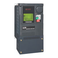
Toshiba H9 ASD Installation And Operation Manual (287 pages)
Adjustable Low Voltage Heavy Duty Industrial Speed Drive
Brand:
Toshiba
| Category:
Network Card
| Size: 3.64 MB
Table of Contents
Important Notice
3
About this Manual
4
Table of Contents
6
General Safety Information
8
Safety Alert Symbol
8
Signal Words
8
Special Symbols
9
Equipment Warning Labels
9
Qualified Personnel
9
Equipment Inspection
10
Handling and Storage
10
Disposal
10
Installation Precautions
11
Location and Ambient Requirements
11
Mounting Requirements
11
Conductor Routing and Grounding
12
Grounding Capacitor Switch
12
Power Connections
13
Protection
13
System Integration Precautions
14
Personnel Protection
14
System Setup Requirements
15
Operational and Maintenance Precautions
16
Motor Characteristics
17
Motor Autotuning
17
Pulse Width Modulation Operation
17
Low-Speed Operation
17
Overload Protection Adjustment
17
Operation above 60 Hz
17
Power Factor Correction
18
Light Load Conditions
18
Motor/Load Combinations
18
Load-Produced Negative Torque
19
Motor Braking
19
ASD Characteristics
20
Over-Current Protection
20
ASD Capacity
20
Using Vector Control
20
Installation and Connections
21
Mounting the ASD
22
Enclosure and Conduit Plate Dimensions
22
Connecting the ASD
23
Power Connection Requirements
24
System Grounding
25
Grounding Capacitor
25
Lead Length Specifications
27
I/O and Control
28
Terminal Board Terminal Names and Functions
28
Terminal Descriptions
29
Terminal Board
31
Default Setting
31
I/O Circuit Configurations
32
Typical Connection Diagram
33
Startup and Test
34
Electronic Operator Interface
35
EOI Operation
35
Battery Backup
35
LED/LCD Screen Installation Note
35
EOI Remote Mounting
36
EOI Features
37
LED/LCD Screen
38
LED Character/Font Information
38
LCD Character/Font Information
38
LCD Screen
39
Primary Menus of the LCD Screen
39
Frequency Command Screen
39
Monitor Screen/Program Menu Screen
39
Remote EOI Hardware
40
EOI Mounting Hardware
40
Bezel Plate Mounting Hardware
40
EOI Installation Precautions
41
EOI Remote Mounting W/O the ASD-MTG-KIT9
41
EOI Mounting Dimensions
41
EOI Remote Mounting Using the ASD-MTG-KIT9
42
EOI ASD-MTG-KIT9 Mounting Dimensions
42
Command Mode and Frequency Mode Control
43
Command Control (F003)
43
Frequency Control (F004)
44
Command and Frequency Control Selections
44
Override Operation
45
Command and Frequency-Control Override Hierarchy
45
Command Control Selections
46
Frequency Control Selections
46
System Configuration and Menu Options
48
Root Menus
48
Frequency Command Mode
48
Frequency Setting
48
EOI Command Mode
49
Monitor Mode
50
Main Monitor Selections
52
Program Mode Menu Navigation
53
Jump Frequencies
64
Communication Settings
71
System Operation
77
Startup Wizard Parameters
77
Initial Setup
77
Startup Wizard Parameter Requirements
78
Upper-Limit Frequency/Lower-Limit Frequency
78
Automatic Acceleration/Deceleration
78
Acceleration Time
78
Deceleration Time
79
Command Source
79
Operation (Local)
80
Frequency Reference Source
80
Default Setting Changes
81
Save User Settings
82
Direct Access Parameter Information
83
Direct Access Parameters/Numbers
83
Command Mode Selection
84
FM Output Terminal Adjustment
85
FM Output Terminal Function
85
Forward/Reverse Run Selection
86
Type Reset
86
Acceleration
87
Maximum Frequency
87
Base Frequency 1
88
Lower-Limit Frequency
88
Upper-Limit Frequency
88
V/F Pattern
88
Manual Torque Boost 1
89
Motor Overload Protection Configuration
89
Preset Speed
90
Automatic Function Selection
92
Forward/Reverse Run Priority Selection
93
Low-Speed Signal Output Frequency
93
Speed Reach Detection Band
93
Speed Reach Frequency
93
16-Bit Binary/Bcd Input
94
Input Terminal Priority
94
Always on Terminal 1
95
Input Terminal 1 (F) Function
95
Input Terminal 2 (R) Function/Input Terminal 3 (ST) Function
95
Option V/I Terminal Voltage/Current Selection
95
Input Terminal 4-16 Functions
96
Output Terminal 1-9 Functions
99
Input Terminal 1-20 Response Time
102
Input Terminal Functions
102
Base Frequency 2
105
Base Frequency Voltage 2
105
Manual Torque Boost 2
105
Motor Overload Protection Level 2
105
Base Frequency 3
106
Base Frequency Voltage 3
106
Manual Torque Boost 3
106
Motor Overload Protection Level 3
106
Base Frequency 4
107
Base Frequency Voltage 4
107
Manual Torque Boost 4
107
Motor Overload Protection Level 4
107
V/F 5-Point Setting Frequency 1
108
V/F 5-Point Setting Frequency 2
109
V/F 5-Point Setting Voltage 1
109
V/F 5-Point Setting Frequency 4
110
V/F 5-Point Setting Voltage 2 / V/F 5-Point Setting Frequency 3
110
V/F 5-Point Setting Voltage 3
110
V/F 5-Point Setting Voltage 4
110
Frequency Priority Selection
111
V/F 5-Point Setting Frequency 5
111
V/F 5-Point Setting Voltage 5
111
Speed Control
112
V/I Input Point 1 Setting
112
V/I Input Speed Control Setup
112
V/I Input Point 1 Frequency
113
V/I Input Point 2 Frequency
113
V/I Input Point 2 Setting
113
V/I Input Point 1 Rate
114
V/I Input Torque Control Setup
114
Frequency Mode 2
115
Frequency Mode Priority Switching Frequency
115
V/I Input Point 2 Rate
115
Analog Input Filter
116
RR Input Point 1 Frequency
117
RR Input Point 1 Setting
117
RR Input Speed Control Setup
117
RR Input Point 2 Frequency
118
RR Input Point 2 Setting
118
RR Input Point 1 Rate
119
RR Input Point 2 Rate
119
RR Input Torque Control Setup
119
RX Input Point 1 Frequency
120
RX Input Point 1 Setting
120
RX Input Speed Control Setup
120
RX Input Point 2 Frequency
121
RX Input Point 2 Setting
121
RX Input Point 1 Rate
122
RX Input Point 2 Rate
122
RX Input Torque Control Setup
122
RX2 (AI1) Input Point 1 Setting
123
RX2 (AI1) Input Speed Control Setup
123
RX2 (AI1) Input Point 1 Frequency
124
RX2 (AI1) Input Point 2 Frequency
124
RX2 (AI1) Input Point 2 Setting
124
RX2 (AI1) Input Point 1 Rate
125
RX2 (AI1) Input Torque Control Setup
125
RX2 (AI1) Input Point 2 Rate
126
BIN Input Point 1 Setting
127
BIN Input Speed Control Setup
127
BIN Input Point 1 Frequency
128
BIN Input Point 2 Frequency
128
BIN Input Point 2 Setting
128
PG Input Point 1 Frequency
129
PG Input Point 1 Setting
129
PG Input Speed Control Setup
129
PG Input Point 2 Frequency
130
PG Input Point 2 Setting
130
Run Frequency
130
0 Hz Dead Band Signal
131
DC Injection Braking
131
End Frequency
131
Run Frequency Hysteresis
131
0 Hz Command Output/Time Limit for Lower-Limit Frequency Operation
132
DC Injection Braking Time
132
Forward/Reverse DC Injection Braking Priority
132
Motor Shaft Fixing Control
132
Jog Frequency
133
Jog Setup and Execution
133
EOI (Panel) Operation Jog Mode
134
Jog Stop Pattern
134
UP/DOWN Frequency (Up) Response Time
135
Initial UP/DOWN Frequency
136
UP/DOWN Frequency (Down) Frequency Step
136
UP/DOWN Frequency (Down) Response Time
136
UP/DOWN Frequency (Up) Frequency Step
136
Up/Down Frequency Operation Control Timing Diagram
137
Jump Frequency 1 Bandwidth
138
Jump Frequency 2
138
Jump Frequency 3 Bandwidth
138
Preset Speeds
138
Auto Restart Selection
140
PWM Carrier Frequency
140
Regenerative Power Ridethrough Mode
141
Ridethrough Setup Requirements
141
Retry Selection
142
Dynamic Braking
143
Over-Voltage Limit Operation
143
Continuous Dynamic Braking Capacity
144
Dynamic Braking Resistance
144
Ridethrough Time
144
Supply Voltage Correction
144
Carrier Frequency Control Mode
145
Forward Run/Reverse Run Disable
145
Random Mode
145
Synchronized Deceleration Time
145
Drooping Gain
146
Speed at 0% Drooping Gain
146
Speed at F320 Drooping Gain
146
Synchronized Acceleration Time
146
Drooping Insensitive Torque
147
Drooping Output Filter
147
Light-Load High-Speed Learning Function
147
Light-Load High-Speed Operation
147
Automatic Light-Load High-Speed Operation Frequency
148
Light-Load High-Speed Operation Detection Time
148
Light-Load High-Speed Operation Load Wait Time
148
Light-Load High-Speed Operation Switching Lower-Limit Frequency
148
Heavy-Load Torque During Constant Power Running
149
Heavy-Load Torque During Power Running
149
Switching Load Torque During Power Running
149
Switching Load Torque During Regenerative Braking
149
Creeping Frequency
150
Panel Torque Bias/Panel Torque Gain
150
Release Time
150
Torque Bias Input Selection
150
Accel/Decel Suspend
151
Braking Time Learning Function
151
Creeping Time
151
Acceleration Suspend Frequency
152
Acceleration Suspend Time
152
Deceleration Suspend Frequency
152
Deceleration Suspend Time
152
Commercial Power/Asd Output Switching
153
ASD Side-Switching Wait Time
154
Commercial Power Switching Wait Time/Freq. Hold Time
154
Commercial Power/Asd Switching Frequency
154
PID Control Switching
154
PID Feedback Delay Filter
155
PID Feedback Integral (I) Gain/Pid Deviation Upper-Limit
155
PID Feedback Proportional (P) Gain
155
PID Feedback Signal
155
PID Control Wait Time/Pid Output Upper-Limit
156
PID Deviation Lower-Limit
156
PID Feedback Differential (D) Gain
156
Process Upper-Limit/Process Lower-Limit
156
Number of PG Input Phases
157
Number of PG Input Pulses
157
PID Output Lower-Limit
157
Process Increasing Rate/Process Decreasing Rate
157
Autotuning 1
158
PG Disconnection Detection
158
Simple Positioning Completion Range
158
Slip Frequency Gain
158
Autotuning 2
159
Base Frequency Voltage 1
159
Motor Rated Capacity
159
Motor Rated Current/Rpm
159
Exciting Strengthening Coefficient
160
Motor Constant 1 (Torque Boost)
160
Motor Constant 2 (No-Load Current)
160
Motor Constant 3 (Leak Inductance)
160
Stall Prevention Factor 1
161
Tension Torque Bias Input
161
Torque Command Selection
161
Forward Speed Limit Input
162
Forward Speed Limit Level
162
Load Sharing Gain Input
162
Reverse Speed Limit Input
163
Speed Limit (Torque=0) Center Value
163
Speed Limit (Torque=0) Center Value Reference
163
Power Running Torque Limit 1
164
Rotation in Specified Direction ONLY
164
Speed Limit (Torque=0) Band
164
Power Running Torque Limit 2 Level
165
Power Running Torque Limit 3 Level
165
Regenerative Braking Torque Limit 1
165
Regenerative Braking Torque Limit 2 Level
165
Accel/Decel Operation after Torque Limit
166
Power Running Stall Continuous Trip Detection Time
166
Regenerative Braking Torque Limit 3 Level
166
Regenerative Braking Torque Limit 4 Level
166
Current Control Proportional Gain
167
Speed Loop Proportional Gain
167
Speed Loop Stabilization Coefficient
167
Stall Prevention During Regeneration
167
Load Moment of Inertia 2
168
Second Speed Loop Stabilization Coefficient
168
Speed PID Switching Frequency
168
V/I Input Bias / V/I Input Gain
168
RR Input Bias
169
RR Input Gain
169
RX Input Bias
169
RX Input Gain
169
AI2 (Option V/I) Input Bias
170
AI2 (Option V/I) Input Gain
170
RX2 (AI1) Input Bias
170
RX2 (AI1) Input Gain
170
Acceleration Time 2
171
Deceleration Time 2
171
Permanent Magnet (PM) Motor Constant 1/2
171
Acc/Dec Pattern 1
172
Acc/Dec Pattern 2
173
Acc/Dec Pattern 1 – 4
174
Accel/Decel Switching Frequency 1
174
Acceleration Time 3
175
S-Pattern Acceleration Lower-Limit/Upper-Limit Adjustment
175
S-Pattern Deceleration Lower-Limit Adjustment
175
S-Pattern Deceleration Upper-Limit Adjustment
175
Acceleration Time 4
176
Acceleration/Deceleration Pattern 3
176
Acceleration/Deceleration Switching Frequency 2
176
Deceleration Time 3
176
Acceleration/Deceleration Pattern 4
177
Acceleration/Deceleration Switching Frequency 3
177
Deceleration Time 4
177
Pattern Operation Selection/Pattern Operation Mode
177
Pattern 1 Repeat
178
Pattern Group 1
179
Pattern Run Setup (for Pattern Group 1)
179
Pattern 2 Repeat
181
Pattern Group 2
182
Speed 1-15 Operation Time
184
Preset Speed Operation Mode
186
Motor Overload Protection Level 1
189
Retain Trip Record at Power down
189
Stall Prevention Level
189
ASD Output Phase Failure Detection
190
Emergency off DC Injection Application Time
190
Emergency off Mode Settings
190
ASD Input Phase Failure Detection
191
Low-Current Detection Current Hysteresis Width/Low-Current Trip
191
Motor 150% Overload Time Limit
191
Overload Reduction Starting Frequency
191
Low-Current Detection Threshold
192
Low-Current Trip Threshold Time
192
Over-Torque Trip
192
Short Circuit Detection at Start
192
Cooling Fan Control
193
Cumulative Operation Time Alarm
193
Over-Torque Detection Level
193
Over-Torque Detection Time
193
Abnormal Speed Detection Time
194
Over-Speed Detection Frequency Upper Band/Lower Band
194
Over-Voltage Limit Operation Level
194
Under-Voltage Trip
194
ASD Overload
195
Brake Answer Wait Time
195
Regenerative Power Ridethrough Control Level
195
Under-Voltage Trip Detection Time
195
Annual Average Ambient Temperature
196
PTC1 Thermal Selection
196
Rush Relay Current Activation Time
196
V/I Analog Input Broken Wire Detection Level
196
Braking Resistance Overload Time (10X Rated Torque)
197
PTC2 Thermal Selection
197
Step-Out Current Detection Level
197
Step-Out Current Detection Time
197
Adding Input Selection
198
Multiplying Input Selection
198
AM Output Terminal Adjustment
199
AM Output Terminal Function
199
MON1 Terminal Meter Selection
199
FP Terminal Assignment
200
MON1 Terminal Adjustment
200
MON2 Terminal Adjustment
200
MON2 Terminal Meter Selection
200
FM Bias Adjustment/Am Output Gradient Characteristic
201
FM Output Gradient Characteristic
201
FM Voltage/Current Output Switching
201
Pulse Output Frequency
201
AM Bias Adjustment
202
MON 1 Output Gradient Characteristic/Mon 1 Bias Adjustment
202
MON 1 Voltage/Current Output Switching
202
MON 2 Voltage/Current Output Switching
202
Display Unit Multiplication Factor
203
Display Units for Voltage and Current
203
MON 2 Output Gradient Characteristic/Mon 2 Bias Adjustment
203
Parameter Write Lock out
203
Change Step Selection 1
204
Display Bias
204
Display Gradient Characteristic
204
Display Unit Selection
204
Change Step Selection 2
205
Operation Command Clear Selection When ST off
205
Panel Stop Pattern
205
Panel Frequency Lock Out/Panel Emergency off Lock out
206
Panel Load Sharing Gain
206
Panel Override Multiplication Gain
206
Panel Torque Command/Panel Tension Torque Bias
206
Command Mode/Frequency Mode Change Lock out
207
Lock out All Keys
207
Panel Reset Lock out
207
Trace Selection
207
Trace Cycle
208
Trace Data
208
ASD Number
209
Baud Rate (RS485 2-Wire)
209
Communications Time-Out Time (RS485 2- and 4-Wire)
209
Parity (RS485 2- and 4-Wire)
209
Communications Time-Out Action (RS485 2- and 4-Wire)
210
Send Wait Time (RS485 2-Wire)
210
ASD-To-ASD Communications (RS485 2-Wire)
211
Frequency Point Selection
211
RS485 2-Wire Protocol Selection
211
Figure 35-G
212
Point 1 Frequency
212
Point 1 Setting
212
Point 2 Setting
212
Baud Rate (RS485)
213
Point 2 Frequency
213
RS485 Send Wait Time (RS485)
213
ASD-To-ASD Communications (RS485)
214
Communications Option (Devicenet/Profibus) Settings
214
RS485 Protocol Selection (Tsb/Modbus)
214
ASD Operation at Disconnect
217
Communications Option Station Address Monitor
217
Disconnection Detection Extended Time
217
Preset Speed Operation Selection
217
Block Write Data
218
Communications Option Speed Switch Monitor Devicenet/CC-Link
218
Block Read Data
219
Free Notes
220
Input Function Command 1
220
Input Function Target 1
220
Network Option Reset Settings
220
Input Function Command 2
221
Input Function Target 2
221
Input Function Target 3
221
Output Function Assigned
221
Input Function Commands
222
Input Function Targets
222
My Function Percent Data
224
My Function Frequency Data
225
My Function Time Data
226
Input Function Target
227
My Function Count Data
227
Input Function Command
228
Analog Function Assigned Object 11
233
Analog Input Function Target 11
233
Analog Input Function Target 21
233
Analog Function Assigned Object 21
234
Monitor Output Function 11
234
Monitor Output Function Command 11
234
Monitor Output Function 21
235
Monitor Output Function 31
235
Monitor Output Function Command 21
235
Monitor Output Function 41
236
Monitor Output Function Command 31
236
Monitor Output Function Command 41
236
Virtual Input Terminal Selection
237
My Function Selection
238
Traverse Acceleration Time/Traverse Deceleration Time
240
Traverse Jump Step
240
Traverse Selection
240
Traverse Step
240
Discrete Input Terminal Assignment Selections and Descriptions
241
Output Terminal Assignments for FP, AM, FM, MON1/MON2 Output Terminals
244
My Function Input Function Target Selections
245
My Function Input Setting Assignments, and Parameter/Input
246
Output Terminal Assignments
246
Trace Back Data Selections
247
Input Function Target Selections, Associated Communications Number
248
My Function Operator Selections
250
Alarms, Trips, and Troubleshooting
251
User Notification Codes
252
Alarms
253
Trips/Faults
255
Viewing Trip Information
260
Trip Record at Monitor Screen
260
Trip History
260
Clearing a Trip
260
Enclosure and Conduit Plate Dimensions
261
460-Volt H9 ASD Systems
262
Conduit Plate
262
D E R1 R2
262
Enclosure Figure Number
262
Figure 34-A
262
Figure 34-B
262
Conduit Plate Dimensions
266
Figure 31
262
Model Number VT130H9U
262
Mounting Hole Dimensions (In/MM)
262
Width Height Depth
262
Current/Voltage Specifications
269
460-Volt Chassis Standard Ratings Table
270
Cable/Terminal/Torque Specifications
271
212K
271
Dynamic Braking System Specifications
273
Braking Resistor Circuit with a Thermal Fuse
274
Short Circuit Protection Recommendations
275
H9 ASD Optional Devices
276
Index
277
Advertisement
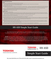
Toshiba H9 ASD Simple Start Manual (4 pages)
Brand:
Toshiba
| Category:
Engine
| Size: 0.9 MB
Advertisement
Related Products
Toshiba H9
Toshiba TEC H-9100N-US
Toshiba TEC H-9100N-CA
Toshiba HD-XA1 - HD DVD Player
Toshiba HD-A20KC
Toshiba HWS-1403H8R-E
Toshiba HWS-805XWHT9-E
Toshiba HWS-P1105XWHT6-E
Toshiba HWT-401HW-E
Toshiba HWT-1401H8W-E
Toshiba Categories
Laptop
Air Conditioner
TV
LCD TV
All in One Printer
More Toshiba Manuals
Login
Sign In
OR
Sign in with Facebook
Sign in with Google
Upload manual
Upload from disk
Upload from URL