Sign In
Upload
Manuals
Brands
Toro Manuals
Lawn Mower
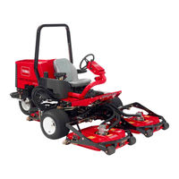
Groundsmaster 3500 30809
Toro Groundsmaster 3500 30809 Manuals
Manuals and User Guides for Toro Groundsmaster 3500 30809. We have
1
Toro Groundsmaster 3500 30809 manual available for free PDF download: Service Manual
Toro Groundsmaster 3500 30809 Service Manual (283 pages)
Brand:
Toro
| Category:
Lawn Mower
| Size: 12.38 MB
Table of Contents
This Page Is Intentionally Blank.
7
Table of Contents
7
Chapter 1 - Safety
9
General Safety Instructions
9
Jacking Instructions
12
Safety and Instruction Decals
13
Chapter 2 Product Records and Maintenance
15
Maintenance
15
Product Records
15
Equivalents and Conversions
16
Torque Specifications
17
Fastener Identification
17
Chapter 3 - Kubota Diesel Engine
20
Specifications
20
Other Torque Specifications
20
Conversion Factors
20
Chapter 3 Kubota Diesel Engine
21
05 Series
21
Specifications
23
Introduction
21
Kubota Workshop Manual, Diesel Engine
21
Service and Repairs
21
Introduction
24
Operator's Manuals
24
Kubota Workshop Manual
24
Kubota Diesel Engine
24
Air Cleaner and Muffler
26
Check Air Filter, Dust Cup, & Burp Valve
27
Muffler Installation
27
Muffler Removal
27
Fuel System
28
Clean Fuel Tank
29
Fuel Tank Installation
29
Fuel Tank Removal
29
Radiator
30
Installation
32
Removal
32
Diesel Engine
34
Removal
35
Installation
37
Chapter 4 Kubota Gasoline Engine
39
Specifications
41
Introduction
42
Operators Manuals
42
Kubota Workshop and Diagnostics Manuals
42
Kubota Gasoline Engine
42
Service and Repairs
44
Air Cleaner and Muffler
44
Check Air Filter, Dust Cup, & Burp Valve
45
Muffler Installation
45
Muffler Removal
45
Fuel System
46
Cleaning Fuel Tank
47
Fuel Tank Installation
47
Fuel Tank Removal
47
Fuel Evaporative Control System
48
Carbon Canister Installation
49
Carbon Canister Removal
49
Radiator/Hydraulic Fluid Cooler
50
Radiator Installation
51
Radiator Removal
51
Engine
54
Engine Removal
55
Engine Installation
57
Chapter 5 Hydraulic System
59
Chapter 4 - Kubota Gasoline Engine
60
Specifications
60
General Information
61
Operator's Manual
61
Relieving Hydraulic System Pressure
61
Traction Circuit Component Failure
61
Hydraulic Hoses
62
Hydraulic Hose and Tube Installation (O−Ring Face Seal Fitting)
63
Hydraulic Fitting Installation (SAE Straight Thread O−Ring Fitting into Component Port)
64
Special Tools
66
Hydraulic Schematics
72
Hydraulic Flow Diagrams
74
Traction Circuit
75
Cutting Unit Circuit
78
Lift Circuit (Up)
81
Lift Circuit (Down) & Counterbalance
83
Sidewinder Circuit
85
Steering Circuit
87
Troubleshooting
88
General Hydraulic System Problems
88
Traction Circuit Problems
89
Lift Circuit Problems
90
Mow Circuit Problems
91
Steering Circuit Problems
91
Testing
92
Piston Pump/Hydrostat (P3) Flow & Relief Pressure Test
100
Cutting Deck Circuit Testing
104
Pressure Test
105
Manifold Relief Valve Pressure Test
112
Steering/Lift/Sidewinder Circuit Testing
116
Relief Valve Pressure Test
121
Steering Control Valve and Steering Cylinder Test
122
Adjustments
124
Unit Serial No. 314000001 & up
127
Counterbalance Logic Valve (LC1) Adjustment
127
Service and Repairs
128
General Precautions for Removing and Installing Hydraulic System Components
128
Check Hydraulic Lines and Hoses
129
Priming Hydraulic Pumps
129
Flush Hydraulic System
130
Filtering Closed Loop Traction Circuit
131
Charge Hydraulic System
132
Hydraulic Tank and Hydraulic Fluid Filter
134
Hydraulic Fluid Cooler
136
Piston Pump/Hydrostat Assembly
138
Piston Pump/Hydrostat Service
146
Gear Pump
150
Gear Pump Service
152
Front Wheel Motors
154
Rear Wheel Motor
156
Wheel Motor Service
158
Hydraulic Manifold
160
Hydraulic Manifold (Unit Serial no 314000001 & Up)
160
Hydraulic Manifold Service
164
Cutting Deck Motors
167
Cutting Deck Motor Service
168
Steering Control Valve
172
Steering Control Valve Service
174
Steering Cylinder
176
Steering Cylinder Service
178
Lift/Sidewinder Control Valve
180
Lift/Sidewinder Control Valve Service
182
Front Lift Cylinder
186
Rear Lift Cylinder
188
Lift Cylinder Service
190
Sidewinder
192
Chapter 6 Electrical System
195
General Information
196
Operator's Manual
196
Electrical Drawings
196
Kubota Diesel Engine − Electrical Components
196
Standard Control Module (SCM)
196
Kubota Gasoline Engine − Electrical Components
197
Special Tools
198
Troubleshooting
200
Starting Problems
200
General Run & Transport Problems
202
Cutting Deck Operating Problems
203
Electrical System Quick Checks
204
Battery Test (Open Circuit Test)
204
Charging System Test
204
Glow Plug System Test (Diesel Engine Only)
204
Check Operation of Interlock Switches
205
Standard Control Module (SCM)
206
Component Testing
208
Ignition Switch
208
Glow Controller (Diesel Engine Only)
209
Glow Relay (Diesel Engine Only)
210
Hour Meter
210
Diode Assemblies
211
CAN- Bus Termination Resistor (Gasoline Engines Only)
211
Indicator Lights
212
PTO Switch
213
Neutral Switch
214
Seat Switch
215
Parking Brake Switch
216
Transport/Mow Switch
216
Fuses
216
Fusible Links
217
Fuel Pump (Diesel Engine Only)
220
Fuel Pump (Gasoline Engine Only)
221
Fuel Stop Solenoid (Diesel Engine Only)
222
Electronic Throttle Control
223
Hydraulic Cartridge Solenoid Valve Coils
224
Service and Repairs
225
Battery Care
225
Battery Service
226
Chapter 7 Wheels, Brakes, and Chassis
231
Special Tools
232
Specifications
232
Adjustments
233
Adjust Brakes
233
Adjust Front Lift Arms
234
Adjust Front Lift Arm Carrier Stop Bracket Assembly
235
Adjust Rear Lift Arm
236
Service and Repairs
238
Standard Seat
238
Deluxe Seat
239
Front Wheel and Brake
240
Rear Fork and Wheel
242
Brake Lever Linkages
244
Steering Column
246
Front Lift Arms
248
Rear Lift Arm
250
Sidewinder Carrier
252
Chapter 8 Cutting Decks
253
Adjustments
253
Service and Repairs
253
Special Tools
253
Specifications
253
General Information
255
Operator's Manual
255
Troubleshooting
256
Factors that Can Affect Quality of Cut
256
Blade Stopping Time
258
Blade Spindle Assembly
260
Blade Spindle Service
262
Rear Roller
264
Rear Roller Service
266
Special Tools
267
Front Roller Service
269
Cutting Deck Carrier Frame
270
Chapter 9 - Foldout Drawings
273
Electrical Schematics and Diagrams
273
Electrical Drawing Designation
273
Electrical Drawing Designations
274
(Units Prior to Serial No. 314000001)
275
(Unit Serial No. 314000001 & Up)
276
Groundsmaster 3500- D Electrical Schematic
277
Groundsmaster 3500- D Harness Diagram
278
Groundsmaster 3500- D Harness Drawing
279
Groundsmaster 3500- G Electrical Schematic
280
Groundsmaster 3500- G Harness Diagram
282
Groundsmaster 3500- G Harness Drawing
283
Hydraulic Schematics
273
Advertisement
Advertisement
Related Products
Toro Groundsmaster 3500-D
Toro 30809 Groundsmaster 3500-G
Toro Groundsmaster 3500
Toro Groundsmaster 3500 30807
Toro Groundsmaster 3505-D
Toro 3550
Toro 3540
Toro 3541
Toro Reelmaster 3555
Toro Reelmaster 3575
Toro Categories
Lawn Mower
Lawn Mower Accessories
Snow Blower
Lawn and Garden Equipment
Utility Vehicle
More Toro Manuals
Login
Sign In
OR
Sign in with Facebook
Sign in with Google
Upload manual
Upload from disk
Upload from URL