Sign In
Upload
Manuals
Brands
Sony Manuals
Receiver
HCD-GPX8G
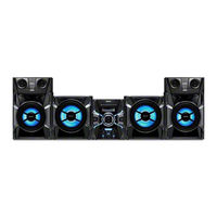
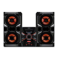
Sony HCD-GPX8G Manuals
Manuals and User Guides for Sony HCD-GPX8G. We have
4
Sony HCD-GPX8G manuals available for free PDF download: Servise Manual, Service Manual
Sony HCD-GPX8G Servise Manual (106 pages)
Brand:
Sony
| Category:
Stereo System
| Size: 13.31 MB
Table of Contents
Specifications
1
Accessories
1
Order of Disassembly
9
Disassembly - Diagrams
10
Panel Disassembly
10
Frontal Disassembly
11
CD (CDM74I-DVBU201//M) Disassembly
11
Tuner 1AM3R Disassembly
12
Main Disassembly
12
4Ch Damp Disassembly
14
Chassis Disassembly
15
Dust CDM Disassembly
16
TICA Disassembly
16
DMB22 Disassembly
17
PLACA Driver, PLACA Switch Disassembly
17
PLACA Sensor Disassembly
18
PLACA Motor Disassembly
18
PLACA Motor (LD) Disassembly
19
Panel Test Mode
20
Common Test Mode
20
Cold Reset
20
Tuner Step Change
20
CD Ship Mode (Without Memory Clear)
21
Factory Preset
21
History Mode
21
Protect Kind Check Test Mode
21
Defect of AMP Circuit
22
Defect of Power Supply Circuit to AMP
22
Electric Check
23
CD Section Check
23
Focus Bias Check
23
FM Auto Stop Check
23
Diagrams
24
CD/USB Diagram
24
MAIN Diagram
25
AMP Diagram
26
Note for Printed Wiring Boards and Schematic Diagrams
28
4CH DAMP Circuit Board
29
Display Circuit Board
34
Main Circuit Board
36
USB Circuit Board
42
Volume Circuit Board
42
MIC Circuit Board
42
USB Schematic Diagram
43
Volume Schematic Diagram
43
MIC Schematic Diagram
43
Driver, Sensor, Switch, Motor (LD), Motor (TB) Circuit Boards
44
Driver, Sensor, Switch, Motor (LD), Motor (TB) Wiring Diagrams
45
Tuner 1AM3R Circuit Board and Wiring Diagram
46
DMB22 Circuit Boards
47
DMB22 Wiring Diagram
48
SMPS 3H384W Schematic Diagram
51
SMPS 3H385W Schematic Diagram
52
Waveforms
53
IC Block Diagrams
54
Ic1405 Njm2903V (Te2) (4Ch Damp Board (2/3))
54
Ic1410, Ic1411 Ba4580Rf-E2 (4Ch Damp Board (2/3))
54
Ic702 Njm2903V (Te2) (Main Board (4/4))
54
Ic1001 Pt6324-Lq (Display Board)
55
IC721 PCM1808PWR (DMB22 Board)
55
IC Src4182 (Dmb22 Board)
56
IC763 PCM1754DBQR (DMB22 Board)
56
IC801 BD8203EFV-E2 (DMB22 Board)
57
Ic701, Ic712 Ba6956An (Driver Board)
57
IC508 S-80829CNNB-B8OT2G (Main Board (1/4))
57
Ic806 R2A15216Fp (Main Board (2/4))
58
Ic101 Rz5B801-0002E2 (Tuner1Am3R Board)
58
Main (1/4) Ic500 R5F3650Kbdfa
59
Dmb22 (2/3) Ic501 Cxd90013R
61
Exploded Views
64
Frontal - Exploded View
65
Chassis Exploded View
67
CD - Exploded View
68
Mechanism Exploded View
69
Electric Parts Lists
70
4CH DAMP Parts List
70
Display Parts List
75
DMB22 Parts List
77
Driver Parts List
80
MAIN Parts List
81
MIC Parts List
86
Motor (TB), Motor (LD) Parts List
87
Sensor Parts List
87
Switch Parts List
87
Tuner1Am3R Parts List
87
USB Parts List
88
Volume Parts List
88
Revision History
105
Advertisement
Sony HCD-GPX8G Service Manual (94 pages)
COMPACT DISC RECEIVER
Brand:
Sony
| Category:
Receiver
| Size: 7.23 MB
Table of Contents
Service Manual
1
Specifications
1
Table of Contents
3
1 Servicing Notes
4
2 Disassembly
8
Disassembly Flow
8
Case
8
Loading Panel
9
Front Panel Section
10
CD Mechanism Section (CDM741-DVBU201//M)
10
TUNER1AM3R Board
11
MAIN Board
11
Back Panel Section
12
4CH DAMP Board
13
Chassis Section
14
Cover Dust CDM
15
Optical Pick up
15
DMB22 Board
16
DRIVER Board, SWITCH Board
16
SENSOR Board
17
MOTOR (TB) Board
17
MOTOR (LD) Board
18
3 Test Mode
19
Factory Preset
20
CD Ship/Tray Lock Mode
20
CDM Aging Mode
20
History Mode
20
Protect Kind Check Test Mode
20
4 Electrical Check
22
5 Diagrams
23
Block Diagram - CD/USB Section
23
Block Diagram - MAIN Section
24
Block Diagram - AMP Section
25
Block Diagram - PANEL/POWER SUPPLY Section
26
4CH DAMP Board (Component Side)
28
4CH DAMP Board (Conductor Side)
29
Schematic Diagram - 4CH DAMP Board (1/3)
30
Schematic Diagram - 4CH DAMP Board (2/3)
31
Schematic Diagram - 4CH DAMP Board (3/3)
32
Printed Wiring Board - DISPLAY Board
33
Schematic Diagram - DISPLAY Board
34
MAIN Board (Component Side)
35
Printed Wiring Board MAIN Board (Component Side)
35
MAIN Board (Conductor Side)
36
Schematic Diagram - MAIN Board (1/4)
37
Schematic Diagram - MAIN Board (2/4)
38
Schematic Diagram - MAIN Board (3/4)
39
Schematic Diagram - MAIN Board (4/4)
40
Printed Wiring Board - USB, VOLUME and MIC Board
41
Schematic Diagram - USB, VOLUME and MIC Board
42
Printed Wiring Board - DRIVER, SENSOR, SWITCH, MOTOR (LD) and MOTOR (TB) Board
43
Schematic Diagram - DRIVER, SENSOR, SWITCH, MOTOR (LD) and MOTOR (TB) Board
44
Printed Wiring Board - TUNER1AM3R Board
45
Schematic Diagram - TUNER1AM3R Board
45
Printed Wiring Board - DMB22 Board
46
Schematic Diagram - DMB22 Board (1/3)
47
Schematic Diagram - DMB22 Board (2/3)
48
Schematic Diagram - DMB22 Board (3/3)
49
IC Block Diagrams
51
6 Exploded Views
61
Case Section
61
Front Panel Section
62
Back Panel Section
63
Chassis Section
64
CD Mechanism Section (1) (CDM74I-DVBU201//M)
65
CD Mechanism Section (2)
66
7 Electrical Parts List
67
Revision History
94
Sony HCD-GPX8G Service Manual (94 pages)
COMPACT DISC RECEIVER
Brand:
Sony
| Category:
Stereo System
| Size: 7.51 MB
Table of Contents
Specifications
1
Leakage Test
2
Table of Contents
3
1 Servicing Notes
4
2 Disassembly
8
Disassembly Flow
8
Case
8
Loading Panel
9
Front Panel Section
10
CD Mechanism Section (CDM741-DVBU201//M)
10
TUNER1AM3R Board
11
MAIN Board
11
Back Panel Section
12
4CH DAMP Board
13
Chassis Section
14
Cover Dust CDM
15
Optical Pick up
15
DMB22 Board
16
DRIVER Board, SWITCH Board
16
SENSOR Board
17
MOTOR (TB) Board
17
MOTOR (LD) Board
18
3 Test Mode
19
4 Electrical Check
22
5 Diagrams
23
Block Diagram - CD/USB Section
23
Block Diagram - MAIN Section
24
Block Diagram - AMP Section
25
Block Diagram - PANEL/POWER SUPPLY Section
26
4CH DAMP Board (Component Side)
28
4CH DAMP Board (Conductor Side)
29
Schematic Diagram - 4CH DAMP Board (1/3)
30
Schematic Diagram - 4CH DAMP Board (2/3)
31
Schematic Diagram - 4CH DAMP Board (3/3)
32
Printed Wiring Board - DISPLAY Board
33
Schematic Diagram - DISPLAY Board
34
MAIN Board (Component Side)
35
Printed Wiring Board MAIN Board (Component Side)
35
MAIN Board (Conductor Side)
36
Schematic Diagram - MAIN Board (1/4)
37
Schematic Diagram - MAIN Board (2/4)
38
Schematic Diagram - MAIN Board (3/4)
39
Schematic Diagram - MAIN Board (4/4)
40
Printed Wiring Board - USB, VOLUME and MIC Board
41
Schematic Diagram - USB, VOLUME and MIC Board
42
Printed Wiring Board - DRIVER, SENSOR, SWITCH, MOTOR (LD) and MOTOR (TB) Board
43
Schematic Diagram - DRIVER, SENSOR, SWITCH, MOTOR (LD) and MOTOR (TB) Board
44
Printed Wiring Board - TUNER1AM3R Board
45
Schematic Diagram - TUNER1AM3R Board
45
Printed Wiring Board - DMB22 Board
46
Schematic Diagram - DMB22 Board (1/3)
47
Schematic Diagram - DMB22 Board (2/3)
48
Schematic Diagram - DMB22 Board (3/3)
49
6 Exploded Views
61
Case Section
61
Front Panel Section
62
Back Panel Section
63
Chassis Section
64
CD Mechanism Section (1) (CDM74I-DVBU201//M)
65
CD Mechanism Section (2)
66
7 Electrical Parts List
67
Revision History
94
Advertisement
Sony HCD-GPX8G Service Manual (94 pages)
Brand:
Sony
| Category:
Car Receiver
| Size: 7.66 MB
Table of Contents
Table of Contents
3
Servicing Notes
4
Disassembly
8
Disassembly Flow
8
Case
9
Loading Panel
9
Front Panel Section
10
CD Mechanism Section (CDM741-DVBU201//M)
10
TUNER1AM3R Board
11
MAIN Board
11
Back Panel Section
12
4CH DAMP Board
13
Chassis Section
14
Cover Dust CDM
15
Optical Pick up
15
DMB22 Board
16
DRIVER Board, SWITCH Board
16
SENSOR Board
17
MOTOR (TB) Board
17
MOTOR (LD) Board
18
Test Mode
19
Electrical Check
22
Diagrams
23
Block Diagram - CD/USB Section
23
Block Diagram - MAIN Section
24
Block Diagram - AMP Section
25
Block Diagram - PANEL/POWER SUPPLY Section
26
4CH DAMP Board (Component Side)
28
4CH DAMP Board (Conductor Side)
29
Schematic Diagram - 4CH DAMP Board (1/3)
30
Schematic Diagram - 4CH DAMP Board (2/3)
31
Schematic Diagram - 4CH DAMP Board (3/3)
32
Printed Wiring Board - DISPLAY Board
33
Schematic Diagram - DISPLAY Board
34
MAIN Board (Component Side)
35
MAIN Board (Conductor Side)
36
Schematic Diagram - MAIN Board (1/4)
37
Schematic Diagram - MAIN Board (2/4)
38
Schematic Diagram - MAIN Board (3/4)
39
Schematic Diagram - MAIN Board (4/4)
40
Printed Wiring Board - USB, VOLUME and MIC Board
41
Schematic Diagram - USB, VOLUME and MIC Board
42
Printed Wiring Board - DRIVER, SENSOR, SWITCH, MOTOR (LD) and MOTOR (TB) Board
43
Schematic Diagram - DRIVER, SENSOR, SWITCH, MOTOR (LD) and MOTOR (TB) Board
44
Printed Wiring Board - TUNER1AM3R Board
45
Schematic Diagram - TUNER1AM3R Board
45
Printed Wiring Board - DMB22 Board
46
Schematic Diagram - DMB22 Board (1/3)
47
Schematic Diagram - DMB22 Board (2/3)
48
Schematic Diagram - DMB22 Board (3/3)
49
Exploded Views
61
Case Section
61
Front Panel Section
62
Back Panel Section
63
Chassis Section
64
CD Mechanism Section (1) (CDM74I-DVBU201//M)
65
CD Mechanism Section (2)
66
Electrical Parts List
67
Advertisement
Related Products
Sony HCD-GPX7G
Sony HCD-GPX5G
Sony HCD-GNZ55D
Sony HCD-GP8D
Sony HCD-GZR88D
Sony HCD-GZR99D
Sony HCD-GZR333IA
Sony HCD-GT3D
Sony HCD-GN1300D
Sony HCD-F500
Sony Categories
Laptop
TV
CD Player
Camcorder
Digital Camera
More Sony Manuals
Login
Sign In
OR
Sign in with Facebook
Sign in with Google
Upload manual
Upload from disk
Upload from URL