Sign In
Upload
Manuals
Brands
Sony Manuals
Receiver
HCD-C990
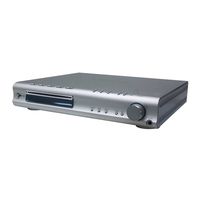
Sony HCD-C990 DVD Dream System Manuals
Manuals and User Guides for Sony HCD-C990 DVD Dream System. We have
2
Sony HCD-C990 DVD Dream System manuals available for free PDF download: Service Manual
Sony HCD-C990 Service Manual (142 pages)
SACD/DVD RECEIVER
Brand:
Sony
| Category:
Receiver
| Size: 11.78 MB
Table of Contents
Service Manual
1
Self Diagnosis Function
2
Table of Contents
4
1 Servicing Notes
5
2 General
6
Location of Controls
6
3 Disassembly
9
Disassembly Flow
9
Front Panel (AL) Section, Side Panel (L)/(R)
10
Mechanism Deck (CDM69-DVBU16)
10
POWER SW Board
11
AUDIO Board, VIDEO Board
11
AMP Board
12
POWER Board
12
DVD Board
13
Optical Pick-Up (DVBU16)
13
Pick-Up Unit (TDP022W)
14
SW Board, Bracket (Top) Assy
14
RELAY Board
15
Motor (Stocker) Assy (Stocker) (M781)
15
Motor (Stocker) Assy (Roller) (M771)
16
Motor (Stocker) Assy (Mode) (M761)
16
Rubber Roller (Slider) Assy
17
Timing Belt (Front/Rear)
17
Cam (Gear)
18
SENSOR Board
18
4 Assembly
19
How to Install the Cam (Eject Lock)
19
How to Install the Cam (Gear)
19
How to Install the Gear (Mode 2)
20
How to Install the Gear (Mode Cam)
20
How to Install the Rotary Encoder (S702), Gear (Stocker Communication)
21
How to Install the Cam (Stocker U/D)
21
How to Install the Stocker Assy
22
Phase Adjustment between Pinions (Slider) and Slider-1 to 5 (L/R)
23
5 Test Mode
24
6 Electrical Adjustment
31
7 Diagrams
32
Block Diagram - RF SERVO Section
32
Block Diagram - AUDIO (DSP) Section
33
Block Diagram - AUDIO OUT, PANEL Section
34
Block Diagram - VIDEO Section
35
Block Diagram - CHANGER, POWER SUPPLY Section
36
Note for Printed Wiring Boards and Schematic Diagrams
37
Printed Wiring Boards - RF Section
38
Schematic Diagram - RF Section
39
Printed Wiring Boards - CHANGER Section
40
Schematic Diagram - CHANGER Section
41
Printed Wiring Board - DVD Board (Component Side)
42
Printed Wiring Board - DVD Board (Conductor Side)
43
Schematic Diagram - DVD Board (1/10)
44
Schematic Diagram - DVD Board (2/10)
45
Schematic Diagram - DVD Board (3/10)
46
Schematic Diagram - DVD Board (4/10)
47
Schematic Diagram - DVD Board (5/10)
48
Schematic Diagram - DVD Board (6/10)
49
Schematic Diagram - DVD Board (7/10)
50
Schematic Diagram - DVD Board (8/10)
51
Schematic Diagram - DVD Board (9/10)
52
Schematic Diagram - DVD Board (10/10)
53
Printed Wiring Board - AMP Section (1/2)
54
Printed Wiring Boards - AMP Section (2/2)
55
Schematic Diagram - AMP Section (1/2)
56
Schematic Diagram - AMP Section (2/2)
57
Printed Wiring Boards - AUDIO Section
58
Schematic Diagram - AUDIO Section
59
Printed Wiring Board - VIDEO Section
60
Schematic Diagram - VIDEO Section
61
Printed Wiring Boards - DC-DC CONVERTER Section
62
Schematic Diagram - DC-DC CONVERTER Section
63
Printed Wiring Boards - CONTROL Section
64
Schematic Diagram - CONTROL Section
65
Printed Wiring Board - FL Board
66
Schematic Diagram - FL Board
67
Printed Wiring Boards - POWER Section (1/2)
68
Printed Wiring Boards - POWER Section (2/2)
69
Schematic Diagram - POWER Section
70
Amp Board
83
Audio Board
85
Video Board
85
IC Pin Function Description
88
8 Exploded Views
107
General Section
107
Front Panel Section-1
108
Front Panel Section-2
109
Chassis Section-1
110
Chassis Section-2
111
Chassis Section-3
112
Mechanism Deck Section-1 (CDM69-DVBU16)
113
Mechanism Deck Section-2 (CDM69-DVBU16)
114
Mechanism Deck Section-3 (CDM69-DVBU16)
115
Mechanism Deck Section-4 (CDM69-DVBU16)
116
Mechanism Deck Section-5 (CDM69-DVBU16)
117
Mechanism Deck Section-6 (CDM69-DVBU16)
118
Optical Pick-Up Section (DVBU16)
119
9 Electrical Parts List
120
Revision History
142
Advertisement
Sony HCD-C990 Service Manual (140 pages)
sacd/dvd receiver
Brand:
Sony
| Category:
Receiver
| Size: 18.19 MB
Table of Contents
Service Manual
1
Self Diagnosis Function
2
Table of Contents
4
1 Servicing Notes
5
2 General
6
Location of Controls
6
3 Disassembly
9
Disassembly Flow
9
Front Panel (AL) Section, Side Panel (L)/(R)
10
Mechanism Deck (CDM69-DVBU16)
10
POWER SW Board
11
AUDIO Board, VIDEO Board
11
AMP Board
12
POWER Board
12
DVD Board
13
Optical Pick-Up (DVBU16)
13
Pick-Up Unit (TDP022W)
14
SW Board, Bracket (Top) Assy
14
RELAY Board
15
Motor (Stocker) Assy (Stocker) (M781)
15
Motor (Stocker) Assy (Roller) (M771)
16
Motor (Stocker) Assy (Mode) (M761)
16
Rubber Roller (Slider) Assy
17
Timing Belt (Front/Rear)
17
Cam (Gear)
18
SENSOR Board
18
How to Install the Cam (Eject Lock)
19
4 Assembly
19
How to Install the Cam (Gear)
19
How to Install the Gear (Mode 2)
20
How to Install the Gear (Mode Cam)
20
How to Install the Rotary Encoder (S702)
21
Gear (Stocker Communication)
21
How to Install the Stocker Assy
21
5 Test Mode
22
6 Diagrams
30
Block Diagram - RF SERVO Section
30
Block Diagram - AUDIO (DSP) Section
31
Block Diagram - AUDIO OUT, PANEL Section
32
Block Diagram - VIDEO Section
33
Block Diagram - CHANGER, POWER SUPPLY Section
34
Note for Printed Wiring Boards and Schematic Diagrams
35
Printed Wiring Boards - RF Section
36
Schematic Diagram - RF Section
37
Printed Wiring Boards - CHANGER Section
38
Schematic Diagram - CHANGER Section
39
Printed Wiring Board - DVD Board (Component Side)
40
Printed Wiring Board - DVD Board (Conductor Side)
41
Schematic Diagram - DVD Board (1/10)
42
Schematic Diagram - DVD Board (2/10)
43
Schematic Diagram - DVD Board (3/10)
44
Schematic Diagram - DVD Board (4/10)
45
Schematic Diagram - DVD Board (5/10)
46
Schematic Diagram - DVD Board (6/10)
47
Schematic Diagram - DVD Board (7/10)
48
Schematic Diagram - DVD Board (8/10)
49
Schematic Diagram - DVD Board (9/10)
50
Schematic Diagram - DVD Board (10/10)
51
Printed Wiring Board - AMP Section (1/2)
52
Printed Wiring Boards - AMP Section (2/2)
53
Schematic Diagram - AMP Section (1/2)
54
Schematic Diagram - AMP Section (2/2)
55
Printed Wiring Boards - AUDIO Section
56
Schematic Diagram - AUDIO Section
57
6-29. Printed Wiring Board - VIDEO Section
58
Schematic Diagram - VIDEO Section
59
Printed Wiring Boards - DC-DC CONVERTER Section
60
Schematic Diagram - DC-DC CONVERTER Section
61
Printed Wiring Boards - CONTROL Section
62
Schematic Diagram - CONTROL Section
63
Printed Wiring Board - FL Board
64
Schematic Diagram - FL Board
65
Printed Wiring Boards - POWER Section (1/2)
66
Printed Wiring Boards - POWER Section (2/2)
67
Schematic Diagram - POWER Section
68
IC Pin Function Description
86
7 Exploded Views
105
General Section
105
Front Panel Section-1
106
Front Panel Section-2
107
Chassis Section-1
108
Q Q 7-5. Chassis Section-2
109
Chassis Section-3
110
Mechanism Deck Section-1 (CDM69-DVBU16)
111
Mechanism Deck Section-2 (CDM69-DVBU16)
112
Mechanism Deck Section-3 (CDM69-DVBU16)
113
Mechanism Deck Section-4 (CDM69-DVBU16)
114
Mechanism Deck Section-5 (CDM69-DVBU16)
115
Mechanism Deck Section-6 (CDM69-DVBU16)
116
Optical Pick-Up Section (DVBU16)
117
8 Electrical Parts List
118
Advertisement
Related Products
Sony HCD-CX5iP
Sony HCD-FLX7D
Sony HCD-SB200
Sony HCD-FR9
Sony HCD-SR4W
Sony HCD-DZ265K
Sony HCD-HDZ284
Sony HCD-HDZ485
Sony HCD-DZ860W
Sony HCD-FX900KW
Sony Categories
Laptop
TV
CD Player
Camcorder
Digital Camera
More Sony Manuals
Login
Sign In
OR
Sign in with Facebook
Sign in with Google
Upload manual
Upload from disk
Upload from URL