Sign In
Upload
Manuals
Brands
Sony Manuals
Tape Deck
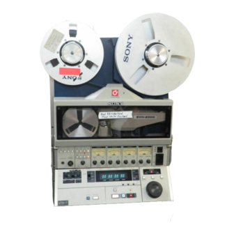
BVH-2000
Sony BVH-2000 Manuals
Manuals and User Guides for Sony BVH-2000. We have
1
Sony BVH-2000 manual available for free PDF download: Operation And Maintenance Manual
Sony BVH-2000 Operation And Maintenance Manual (506 pages)
Videocorder
Brand:
Sony
| Category:
Tape Deck
| Size: 253.39 MB
Table of Contents
Confidental
2
Table of Contents
5
Operation
11
Features
11
Compact and Lightweight
11
Rational VTR System
11
Specifications
12
High Picture and Sound Qualities
12
High Reliability
12
Alarm Functions
12
Dimensions
14
Optional Parts and Accessories
15
Function Control Panels
15
BKH-2014 Side Panel Kit
16
BKH-2015/BKH-2015A Time Code Generator/Reader
16
BKH-2100 Digital Time Base Corrector
17
BKH-2016 CCJ Converter
17
BK-5005 BVE-5000 Interface Board
17
Rack Options
19
Location and Function of Parts
20
Level Control Panel
21
Level Control Panel Peripherals
24
Function Control Panel
25
Tape/Ee Selector
26
Video
26
Audio
27
Shuttle Mode
40
Jog Mode
40
Program Jog Mode
40
Var Button
41
Program Play Mode
41
Edit Function Panel
42
Search Indicator
54
Connector Panel
65
Video Connector Panel
66
TO TBC Connector
68
Switches on the VM-01 Board
68
Audio Connector Panel
69
Remote Control Connector Panel
70
Connections
71
Preadjustment
72
Record Bias
72
REC/PB Level Preset
73
Board Adjustment
74
Opening
74
Board Extraction and Inspection
75
AU-27 Board
76
AE-03 Board
77
EQ-02 Board
78
DM-25 Board
79
MD-14 Board
80
TC-14 Board
83
SY-79 Board
84
Adjusting the Record Current Level on the BVH-2000
84
Adjustment of the Video Head
84
Adjustment of the Sync Head
84
SY-80 Board
85
SV-43 Board
86
RL-12 Board
87
CD-17 Board
88
SR-15 Board
89
DT-04 Board
90
Tape Threading
91
Recording
92
Playback
92
Normal Speed Playback
92
Shuttle
93
Jog
94
Program Jog
95
Program Play
96
Var Memory
97
Capstan Override
98
Standby Mode for the VAR Memory Playback
98
Manual Editing
99
Assemble Editing
99
Insert Editing
100
Spot Erase
101
Auto Editing
102
Basic Operation
102
Audio Split Editing
104
Editing with Two Vtr's
105
Editing Monitor
107
Video Monitor
107
Head Selector in R/P Head Position
107
Audio Monitor
107
Flashing and Lighting of Lamps in Auto Edit Mode
108
Audio Split Edit Area
109
VAR Memory Mode Editing
110
Out Point Preview
111
Editing with One VTR
111
Preroll
112
When Auto Mode Is Turned off
112
When Auto Mode Is Turned on
112
Parallel Operation
113
Alarm
113
Installation
115
Unpacking and Repacking
115
Accessories Supplied
116
Matching Connectors and Cables
117
Power Requirements
117
Installation Conditions
117
Installation Space
118
External Dimensions
118
Working Specs
119
Mounting Function Control Panel
125
Removing Blank Panel
125
Rack Mounting
126
BVT-2000 Modification
127
Picture Stability at Mode Switching
127
Picture Quality in DT Mode and y ADD ON/OFF Switch
128
Vertical Flactuation in Edit Preset of BVH-2000/2180
129
PB V Signal Detection
133
Video Level Control in Bidirex Mode
133
Function of Switches and Jumpers
134
Index of Switches and Jumpers
134
BVE-5000/P Setting
147
Termination of Remote-2 out
147
Remote Mode of BHV-2000/2180
147
Color Frame Editing Using Plug-In TBC
147
Notes on BVR-1000 Operation
148
Output of Audio-3 Monitor Signal from WFM Output
148
Selection of Time Code Output by Tape/Ee Select Switch
149
Cleaning
151
Demagnetizing of Heads
152
Tracking Check
152
Head Projection Check and Upper Drum Replacement
153
Upper Drum Eccentricity Adj. Gauge
153
Head Protection Measurement
153
Upper Drum Replacement
154
Replacement of Upper Drum Assembly
154
Upper Drum Eccentricity Adjustment
155
Installation of DR-13 Board
155
Replacement of the Head Drum Assembly
156
Preliminary Information
156
Installation of the Head Drum Assembly
157
Clearance Confirmation
158
Drum Speed Adjustment
158
Gap Confirmation
158
Slip Ring and Brush Cleaning and Replacement
159
Cleaning of Slip Ring and Brush
159
Brush Remounting and Pressure Adjustment
159
Slip Ring and Brush Replacement
160
Noise Check
160
Mounting and Pressure Adjustment
160
Replacement of the Slant Guide Assembly
161
Replacement of Entrance Slant Guide Assembly
161
Entrance Slant Guide Assy Position Asj.
162
Replacement of Exit Slant Guide Assembly
163
Reel Motor Replacement
164
S Reel Motor Replacement
165
Brake Band Guide Position Adjustment
166
Link Stopper Position Adjustment
166
Brake Solenoid Position Adjustment
166
Reel Table Height Adjustment
167
FG Duty Cycle Adjustment
167
S Reel Table Height Adjustment
167
S Reel Motor FG Duty Cycle Adjustment
167
S Reel Motor Torque Adjustment
168
Motor Torque Adjustment Value
168
Mechanical Brake Torque Adjustment
169
T Reel Motor Replacement
170
T Reel Motor Torque Adjustment
173
Brake Band Replacement
175
Reel Table Height Confirmation
175
Brake Solenoid Replacement
176
Solenoid Assembly Position Adjustment
176
Brake Position Adjustment
176
Replacement of the S-Tension Arm Assembly
177
Replacement of the T-Tension Arm Assembly
178
Air Damper Adjustment
179
Mini Tension Arm Replacement
180
Parallelism Confirmation for the Mini Tension Arm Shaft
180
Mini Tension Arm Solenoid Replacement
181
Capstan Motor Replacement
182
Pinch Roller Pressure Adjustment
183
Motor FG Duty Cycle Adjustment
183
Motor Speed Adjustment
184
Pinch Roller Replacement
185
Pinch Roller Solenoid Replacement
186
Pinch Roller Solenoid Position Replacement
186
Audio/Ctl R/P Head Replacement
187
Head Assembly Installation
187
Audio/Ctl Monitor Head Replacement
188
Audio/Ctl Erase Head Replacement
189
Other Parts Replacement
190
Roller Assembly Replacement
190
Confirmation of the Tape Path
190
Reed Switch Replacement
191
Tape Path Adjustment after Replacing the Parts
192
Audio/Ctl RIP Head Adjustment
192
Tape Path Check & Adjustment
193
Tape Path Check
193
Guide Height Adjustment
194
Guide Height
195
Supply and Take-Up Reel Table Height Adjustment
196
Guide Roller 1 & 2 Height Adjustment
196
T-Tension Arm Height Adjustment
197
Timer Roller Height Adjustment
197
Guide Post 1 Height Adjustment
197
Taper Guide Height Adjustment
198
Guide Post 3 Height Adjustment
198
Timer Roller Slant Adjustment
198
Tape Tension Adjustment
199
Tape Speed Adjustment
200
Tracking Adjustment
201
Preparation before Adjustment
203
Height Adjustment of Taper Guide
203
Slant Adjustment of Entrance Slant Guide
204
Height Adjustment of Entrance Slant Guide
204
Height Adjustment of Guide Post 3
205
Slant Adjustment of Exit Slant Guide
205
Height Adjustment of Exit Slant Guide
205
Check after Adjustment
206
Self Record/Playback RF Waveform Check
206
CTL Head Position Adjustment
207
PG Phase Adjustment
208
Playback with R/P Head
208
Playback with Play Head
209
Overlap Adjustment
210
Adjustment Points
210
Overlap Check
211
Checking Gap Near to Slant Guide Assy
211
When the Overlap C Is Less than the Specified Value
212
When Overlap C Is out of the Specified Value
212
When Overlap B Is out of the Specified Value
212
Audio/Ctl R/P Head Adjustment
213
Zenith Adjusstment
213
Azimuth Adjustment
214
Height Adjustment
214
Fluctuation Adjustment
215
Audio/Ctl Monitor Head Adjustment
216
Audio/Ctl Erase Head Height Adjustment
219
V/S Erase Head Height Adjustment
220
Service Information
221
Principal Components Location
221
Tape Transport
221
Printed Circuit Board
222
Card Rack
222
Power Supply
225
Opening of the Rear Panels and Top Cover
226
Notes on Power Unit
230
Capacity of AC Power Source
230
Voltage Indication Plate
230
Ventilation/Heat Sink
230
Primary Circuit & Electric Shock
231
Check of AC-39 Board
232
Leds for DC Output Check
232
DC Output Terminals
232
PDS Function
232
Extracting/Inserting Plug in Boards
233
Notes on Repair Parts
233
Safety Related Components Warning
233
Standardization of Parts
233
Maintenance Tools/Fixtures
234
Empty Reel
234
Cleaning Fluid
237
Cleaning Piece
237
Erase Head Spacer
237
Timer Roller Spacer
237
Switching Regulator Adjustment Fixture
238
Brake Adjustment Fixture
238
Guide Flange Fixture
238
Alignment Tape
240
Mounting of Rec Inhibit Switch on Front Panel
241
Frame Wiring
241
Manual Open/Close of Movable Guide
242
Error Messages
243
Sys Err
243
SRV Err
243
Abort
243
Self-Diagnosis Function with Power-On
244
Self-Diagnosis During Normal Operation
245
When VTR Stops with "SYS ERR" Display
245
When VTR Stops with Standby Button Blinking
246
Error/Mode Display by Leds on RL-12 Board
246
Drum Lock/Capstan FG Error
248
Capstan Lock
248
Test Functions of System Control System
249
Test Mode Setting/Canceling
249
Software Version Check
250
Display and Character Generator Test
250
Lamp and Buzzer Test
250
Key and Dial Test
251
Free Run Test
251
Test by Memory Readout
251
Designation and Test of Memory Address
252
Monitor Dispaly of Common Memory
252
Contents of Common Memory Data
253
Function of TEST-2 Switch (S5/CO-17)
267
Function of TEST-3 Switch (S5/CO-17)
267
Theory of Operation
271
Tape Format
272
Audio Signal System
274
Outline of Audio Signal System
274
AP-06/12 Board
274
REC Amplifier
275
Audio/Monitor Amplifier
275
CTL Rec Amplifier
275
LA-02 Board
276
La-02 Board Block Diagram
276
Line Input Amplifier
276
Monitor Selector
276
Bandpass Response
277
Recording Amplifier
277
Playback Amplifier
277
Monitor Amplifier
277
AUD-4/CTL Crosstalk Canceller
279
Time Code System
279
BE-03 Board
280
Audio Bias/Erase Oscillator
280
Video/Ctl Erase Oscillator
280
Audio Erase Amplifier
280
Bias Amplifier
281
Video Signal System
282
Outline of Video Signal System
282
DG Compressor
287
RF Switcher
287
Dropout Detector
287
RP-09 Board
290
VM-01 Board
290
Dynamic Tracking System
292
Outline of DT System
292
Principle of Arbitrary Playback
292
Slant Compensation
292
Tracking Control
293
Track Jump Control
294
DT-04 Board (DT-05 Board in PS Model)
295
Outline of Digital Trace Circuit
295
FHX Doubler
295
H Shift Generator
295
PBVX1 Detector
296
DT V Generator
296
PBVX2 Detector
296
Head Movement Detector
296
V Sync In-Phase Detector
297
H Sync Interval Counter
300
V Sync Phase Detector
301
Jump Signal Generator
301
Slope Error Generator
301
Wobbling Signal Generator
302
Bimorph Drive Signal Generator
302
Head Wobbling Detector
303
Tracking Error Detector
303
Color Information Signal Generator
304
System Control System
306
Outline System Control System
306
Outline of SY-79 Board
306
Ctc
307
Roms
307
Sio
307
Rams
307
Outline of SY-80 Board
308
Cpu
308
Ram
308
Outline of LG Board
309
LG Board Block Diagram
309
Control Panels BKH-2011, 2012, 201
310
Input Control Block
310
Configuration of Key Matrix
311
Reading the Key Data Using the Matrix
311
Display Control Block
312
Outline of Remote Control
313
Common Memory
316
Main Communication Data Area
316
Hard Port Monitor Area
317
Counter Area
317
Common Memory Control
317
System Control/Servo Interface
318
Control Panel/Sy-79 Interface
318
SY-79/Common Memory Interface
318
SY-80/ Servo Interface
319
System Control/Tv Board Interface
321
Data Presetting
321
Time Code/Timer Data Read out
322
TC Write Hard Port Data
322
Timer Display Areaa
322
Servo System
324
Outline of Servo System
324
Outline of Drum Servo System
326
Outline of Capstan Servo System
327
Outline of Reel Servo System
328
Capstan Rotation Detection
331
Rotational Direction Detection
331
Rotational Speed Detection
331
Duration Detection
331
REC CTL and PB CTL Circuits
332
Drum Melocity Loop
333
Drum Rotation Detection
334
PG Phase Detection
334
Drum PG Delay
334
Skew Detection
334
Reel Tension AC Feedback Loop
336
S/T Reels Timer Roller Rotational Speed and Direction Detection
338
Interrupt Signal Generator
338
V Sync Separator
340
H/V Detector
340
Burst Phase Comparator
340
Replacement
350
V/S Erase Head Replacement
350
DME Replacement
351
Tape Path Confirmation
351
Duty Cycle Adjustment
351
Reel Motor Assy Replacement
352
S Reel Motor Assy Replacement
352
T Reel Motor Assy Replacement
357
Lower Drum Assy Replacement
361
Lower Drum Assembly Installation
362
Upper Drum Installation & Eccentricity Adjustment
363
Guide Post Replacement
365
Replacement of Slant Guide Components
366
Assembly of Guide Flange and Guide Post
367
Reassembly of Guide
367
Slant and Height Adjustment
367
Installation of Entrance Slant Guide Assy
368
Check and Adjustment
368
Replacement of Exit Slant Guide Components
369
General Alignment for Alignment
372
Index of Alignment Components
372
Initial Setting
377
V. BLANKING LINE SELECT Switch
377
Initial Setting of the BVH-2000/2180
378
Power Supply Alignment
380
FV-02 Board
381
AC-39 Board
381
PS-14 Board
381
Switching Regulator Operating Check and Adjustment
382
Switching Regulator Adjustment Fixture Installation
382
Board Settings
384
VV-01 Board Setting
385
FV-02 Board Setting
386
AC-39 Board Setting
387
AC-39 Board Part Replacement
387
Load
388
No Load
388
VTR Load
388
Standard Load
388
Power Unit Check and Adjustment Procedure
389
AC Power Capacity Check
390
AC Input Voltage Check
390
Power Unit no Load Voltage Check
390
Relay Switching Check with Power On/Off
390
CT-38 Board Check
391
AC-39 Board Operation Check and Adjustment
391
ST-21 Board Operation Check
392
Surge Current Protection Adjustment
392
Low AC Input Voltage Protector Adjustment
392
High AC Input Voltage Protector Adjustment
392
Operation Check
393
Converter Rectified Output
393
Output Voltage Adjustment
394
FV-03 Board Operation Check and Adjustment
395
Output Power Adjustment
395
Power Unit Loaded Output Voltage Check
397
VV-01 Board Control Input Voltage Check
397
VV-01 Board Motor Drive Voltage Check
397
Tape Path System Alignment
402
S Side Tape Tension Adjustment
408
T Side Tape Tension Adjustment
409
Servo System Alignment
432
Advertisement
Advertisement
Related Products
Sony BVH-2000PS
Sony BVS-V3232
Sony TRINITRON BVM-20E1E
Sony TRINITRON BVM-14E5E
Sony TRINITRON BVM-D9H1E
Sony Trinitron BVM-A32E1WM
Sony BVM-2016P
Sony BVT-2000
Sony BVS-3100P
Sony TRINITRON BVM-8045QD
Sony Categories
Laptop
TV
CD Player
Camcorder
Digital Camera
More Sony Manuals
Login
Sign In
OR
Sign in with Facebook
Sign in with Google
Upload manual
Upload from disk
Upload from URL