Sign In
Upload
Manuals
Brands
Siemens Manuals
Control Unit
SIPROTEC 7SJ61
Siemens SIPROTEC 7SJ61 Manuals
Manuals and User Guides for Siemens SIPROTEC 7SJ61. We have
4
Siemens SIPROTEC 7SJ61 manuals available for free PDF download: Manual, Technical Data Manual
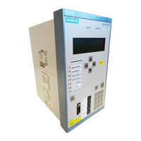
Siemens SIPROTEC 7SJ61 Manual (454 pages)
Multi-functional Protective Relay with Bay Controller
Brand:
Siemens
| Category:
Controller
| Size: 8.82 MB
Table of Contents
Table of Contents
9
Introduction
17
Overall Operation
18
Application Scope
21
Characteristics
23
Functions
27
General
28
Functions Overview
28
Description
28
Setting Notes
29
Settings
30
Device, General Settings
32
Description
32
Setting Notes
32
Settings
33
Information List
33
Power System Data 1
35
Description
35
Setting Notes
35
Settings
40
Information List
41
Oscillographic Fault Records
41
Description
41
Setting Notes
42
Settings
43
Information List
43
Settings Groups
43
Description
43
Setting Notes
44
Settings
44
Information List
44
Power System Data 2
45
Description
45
Setting Notes
45
Settings
46
Information List
46
EN100-Module
47
Functional Description
47
Setting Notes
47
Information List
47
Overcurrent Protection 50, 51, 50N, 51N
48
General
48
Definite Time, High-Set Elements 50-3, 50-2, 50N-3, 50N-2
49
Definite Time Overcurrent Elements 50-1, 50N-1
52
Inverse Time Overcurrent Elements 51, 51N
55
Dynamic Cold Load Pickup Function
58
Inrush Restraint
58
Pickup Logic and Tripping Logic
61
Two-Phase Time Overcurrent Protection
62
Fast Busbar Protection Using Reverse Interlocking
62
Setting Notes
63
Settings
72
Information List
75
Dynamic Cold Load Pickup
77
Description
77
Setting Notes
80
Settings
81
Information List
82
Single-Phase Overcurrent Protection
83
Functional Description
83
High-Impedance Ground Fault Unit Protection
85
Tank Leakage Protection
87
Setting Notes
88
Settings
93
Information List
93
Negative Sequence Protection 46
94
Definite Time Characteristic
94
Inverse Time Characteristic 46-TOC
95
Setting Notes
98
Settings
101
Information List
101
Motor Protection
102
Motor Starting Protection 48
102
Description
102
Setting Notes
105
Motor Restart Inhibit 66
107
Description
107
Setting Notes
113
Load Jam Protection
117
Mode of Operation
117
Setting Notes
120
Motorprotection (Motor Starting Protection 48, Motor Restart Inhibit 66, Loadjam)
122
Settings
122
Information List
123
Thermal Overload Protection 49
124
Description
124
Setting Notes
128
Settings
133
Information List
133
Monitoring Functions
134
Measurement Supervision
134
General
134
Hardware Monitoring
134
Software Monitoring
136
Monitoring of the External Transformer Circuits
137
Setting Notes
138
Settings
139
Information List
139
Trip Circuit Supervision 74TC
140
Description
140
Setting Notes
143
Settings
144
Information List
144
Malfunction Responses of the Monitoring Functions
144
Description
144
Ground Fault Protection 50N(S), 51N(S)
147
Current Elements 50Ns, 51Ns
147
Logic
148
Setting Notes
150
Settings
154
Information List
155
Intermittent Ground Fault Protection
156
Description
156
Setting Notes
160
Settings
161
Information List
161
Automatic Reclosing System 79
162
Program Execution
162
Blocking
167
Status Recognition and Monitoring of the Circuit Breaker
168
Controlling Protection Elements
170
Zone Sequencing (Not Available for Models 7SJ6***-**A**-)
172
Setting Notes
173
Settings
180
Information List
183
Breaker Failure Protection 50BF
185
Description
185
Setting Notes
189
Settings
190
Information List
190
Flexible Protection Functions
191
Function Description
191
Setting Notes
195
Settings
198
Information List
199
Temperature Detection Via RTD Boxes
200
Description
200
Setting Notes
201
Settings
203
Information List
208
Phase Rotation
209
Description
209
Setting Notes
210
Function Logic
211
Pickup Logic of the Entire Device
211
Tripping Logic of the Entire Device
212
Setting Notes
212
Auxiliary Functions
213
Message Processing
213
LED Displays and Binary Outputs (Output Relays)
213
Information on the Integrated Display (LCD) or Personal Computer
214
Information to a Substation Control Center
215
Statistics
216
Description
216
Circuit Breaker Maintenance
217
Motor Statistics
223
Setting Notes
224
Information List
226
Measurement
227
Display of Measured Values
227
Transfer of Measured Values
228
Information List
229
Average Measurements
230
Description
230
Setting Notes
230
Settings
230
Information List
231
Min/Max Measurement Setup
231
Description
231
Setting Notes
231
Settings
231
Information List
232
Set Points for Measured Values
232
Description
233
Setting Notes
233
Information List
233
Set Points for Statistic
234
Description
234
Setting Notes
234
Information List
234
Commissioning Aids
235
Description
235
Web Monitor
237
General
237
Functions
238
Operating Modes
241
Display Example
242
Setting Notes
243
Breaker Control
244
Control Device
244
Description
244
Information List
245
Types of Commands
246
Description
246
Command Sequence
247
Description
247
System Interlocking
248
Description
248
Command Logging
256
Description
256
Mounting and Commissioning
257
Mounting and Connections
258
Configuration Information
258
Hardware Modifications
262
General
262
Disassembly
264
Switch Elements on the Pcbs
266
Interface Modules
276
Reassembly
281
Installation
282
Panel Flush Mounting
282
Rack Mounting and Cubicle Mounting
283
Panel Flush Mounting
284
Checking Connections
285
Checking Data Connections of Serial Interfaces
285
Checking System Connections
288
Commissioning
290
Test Mode and Transmission Block
291
Testing the System Interface
291
Checking the Status of Binary Inputs and Outputs
293
Tests for Circuit Breaker Failure Protection
296
Testing User-Defined Functions
297
Current and Phase Rotation Testing
298
Test for High Impedance Protection
298
Testing the Reverse Interlocking Scheme
299
Checking the Temperature Measurement Via RTD-Box
299
Trip/Close Tests for the Configured Operating Devices
301
Creating Oscillographic Recordings for Tests
302
Final Preparation of the Device
303
Technical Data
305
General Device Data
306
Analog Inputs
306
Auxiliary Voltage
306
Binary Inputs and Outputs
307
Communication Interfaces
309
Electrical Tests
313
Mechanical Stress Tests
315
Climatic Stress Tests
316
Service Conditions
316
Certifications
317
Design
317
Definite-Time Overcurrent Protection 50(N)
318
Inverse-Time Overcurrent Protection 51(N)
320
Inrush Restraint
331
Dynamic Cold Load Pickup
332
Single-Phase Overcurrent Protection
333
Negative Sequence Protection
334
Negative Sequence Protection 46-TOC
335
Motor Starting Protection 48
341
Motor Restart Inhibit 66
342
Load Jam Protection
343
Thermal Overload Protection 49
344
Ground Fault Protection 50N(S), 51N(S)
346
Intermittent Ground Fault Protection
350
Automatic Reclosing System 79
351
Breaker Failure Protection 50BF
352
Flexible Protection Functions
353
Temperature Detection Via RTD Boxes
355
User-Defined Functions (CFC)
356
Additional Functions
361
Breaker Control
365
Dimensions
366
Panel Flush and Cubicle Mounting (Housing Size 1 / 3 )
366
Panel Surface Mounting (Housing Size )
367
Varistor
367
Appendix
369
Ordering Information and Accessories
370
Ordering Information
370
7Sj61 V4.7
370
Accessories
373
Terminal Assignments
376
Housing for Panel Flush and Cubicle Mounting
376
Housing for Panel Surface Mounting
379
Terminal Assignment on Housing for Panel Surface Mounting
382
Assignment of the Female Connectors
384
Connection Examples
385
Connection Examples for Current Transformers, All Devices
385
Connection Examples for RTD-Box, All Devices
389
Current Transformer Requirements
391
Accuracy Limiting Factors
391
Effective and Rated Accuracy Limiting Factor
391
Calculation Example According to IEC 60044-1
391
Class Conversion
392
Cable Core Balance Current Transformer
393
General
393
Requirements
393
Class Accuracy
393
Default Settings
394
Leds
394
Binary Input
394
Binary Output
395
Function Keys
395
Default Display
396
Pre-Defined CFC Charts
397
Protocol-Dependent Functions
399
Functional Scope
400
Settings
402
Information List
415
Group Alarms
433
Measured Values
434
Literature
437
Glossary
439
Index
451
Advertisement
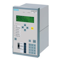
Siemens SIPROTEC 7SJ61 Manual (94 pages)
Input/Output unit, Bay control unit, Communication module, PROFIBUS-DP Communication profile
Brand:
Siemens
| Category:
Protection Device
| Size: 0.65 MB
Table of Contents
Preface
3
Revision Index
7
Table of Contents
9
1 PROFIBUS Communication Modules
11
Communication Module Types and Hardware Revisions
12
Communication Module Types
12
Hardware Revisions
12
Compatibility of the Communication Module Hardware with PROFIBUS-DP Firmware Versions and Mapping Files
13
Display of Module-Specific Information at the SIPROTEC Device
15
Block 1: Status and Parameters of the PROFIBUS-DP Slave
17
Block 2: Firmware Versions and Mapping File
19
Block 3: Module Hardware Information and Boot Firmware Version
20
Block 4: OLM Information
21
Block 5: Status of the Event List Via PROFIBUS-DP
24
2 Parameters and Properties
25
Bus Specific Parameters
26
PROFIBUS-DP Settings
26
Configuration of the Fibre-Optical Interface
28
Event List Settings
31
PROFIBUS-DP Configuration Data
31
Execution of Switching Operations Via PROFIBUS-DP
32
Command Output Modes
32
Transformer Tap Change Commands
33
Behaviour under Special Operating Conditions
33
Response in the Event of Disturbed Communication to the PROFIBUS-DP Master
34
Communication Interruption
34
Signalling of Line-Breaks in a Redundant Fibre-Optical Ring
35
Annunciations to the PROFIBUS-DP Master
37
Event List Via PROFIBUS-DP (Sequence of Events Recorder)
38
Properties of the Event List
39
Structure of a PROFIBUS-DP Telegram with Event List
40
Telegram in Input Direction
40
Telegram in Output Direction
42
Handshake Mechanism
43
3 Data Type Definitions
45
Single-Point Indication (SP, Input)
46
Single Command (SC, Output)
47
Double-Point Indication (DP, Input) / Double Command (DC, Output)
48
Measured Value (Signed Integer)
49
Measured Value (Float)
50
Metered Measurand (Unsigned Long)
51
Transformer Tap Change Command (TC)
52
Transformer Tap Position Indication (TM)
53
Message Block for Event List Via PROFIBUS-DP
54
4 PROFIBUS-DP - Parameterization in DIGSI
57
Interface Selection and Mapping Files
58
Standard Mappings 3-1 to 3-N
58
Compatibility with Standard Mappings of Previous Versions
59
Interface Selection and Mapping Selection in DIGSI 4.21
59
Interface Selection and Mapping Selection in DIGSI 4.3 or Higher
63
Customization of the Allocations
66
Scaling of Measured Values
70
Measurement Conversion
70
Number Representation Depending on the Parameterization
71
Parameterization in DIGSI
73
Time Synchronization
75
PROFIBUS-DP Master
75
Parameterization in DIGSI
77
Using SFC14 and SFC15 in STEP7
79
5 Technical Data
83
Connection Via the PSE Module
84
Connection Via the PSO Module
86
Glossary
89
Index
91
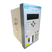
Siemens SIPROTEC 7SJ61 Manual (72 pages)
Multifunction protection with control
Brand:
Siemens
| Category:
Relays
| Size: 0.92 MB
Table of Contents
Preface
3
Table of Contents
7
1 Notes to SIPROTEC Objects
11
Annunciations
12
Error with a Summary Alarm
12
Alarm Summary Event
12
Stop Data Transmission
13
Commands
13
Single Commands
13
Changing the Setting Group
13
Measured Values
14
Metered Measurands
15
2 IEC 60870-5-103 Interoperability
17
Physical Layer
18
Electrical Interface
18
Optical Interface
18
Transmission Speed
18
Link Layer
18
Application Layer
19
Transmission Mode for Application Data
19
Common Address of ASDU
19
Selection of Standard Information Numbers in Monitor Direction
19
System Functions in Monitor Direction
19
Status Indications in Monitor Direction
19
Supervision Indications in Monitor Direction
20
Earth Fault Indications in Monitor Direction
20
Fault Indications in Monitor Direction
21
Auto-Reclosure Indications in Monitor Direction
21
Measurands in Monitor Direction
21
Generic Functions in Monitor Direction
22
Selection of Standard Information Numbers in Control Direction
23
System Functions in Control Direction
23
General Commands in Control Direction
23
Generic Functions in Control Direction
23
Basic Application Functions
23
Miscellaneous
24
3 Point List
25
General Command (Control Direction)
26
Double Point Command
26
Single Point Command
26
User Defined Single Point Command
26
Indications in Monitor Direction
27
Automatic Reclosure Status
27
Time Overcurrent Protection
28
Inrush Function
29
Directional Time Overcurrent Protection
30
Unbalanced Load Protection
31
Frequency Protection
32
Voltage Protection
33
Internal Mode Status
34
Highly Sensitive Earth Fault Protection
36
Trip Coil Monitor
37
Circuit Breaker Failure Protection
37
Thermal Overload Protection
38
Motor Start Protection
38
Start-Up Supervision
38
Control Switches Return Position Indication(Double Point Commands)
39
Output Channels Return Position Indication (Single Point Commands)
39
3.2.17 Free Channels
39
Measurements
42
ASDU3 (Measurements I)
42
ASDU9 (Measurements II)
42
User Defined ASDU9 (Measurements II)
43
Time Tagged Measurements
43
Metering Values
44
Settings
45
Index
69
Glossary
71
Advertisement
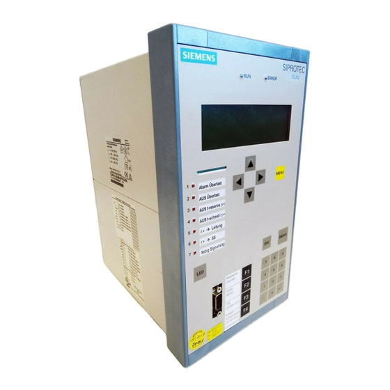
Siemens SIPROTEC 7SJ61 Technical Data Manual (58 pages)
Multifunction protection with control
Brand:
Siemens
| Category:
Control Unit
| Size: 0.26 MB
Table of Contents
Table of Contents
7
1 Bus Specific Parameters
11
2 Supported Modbus Functions
13
Table 2-1 Supported Modbus Functions
14
3 Exception Responses of the Modbus Slave
15
4 Annunciations to the Modbus Master
17
5 Data Type Definitions
19
Single Command (SC) / Single-Point Indiation (SP)
20
Double Command (DC) / Double-Point Indication (DP)
20
Figure 5-1 Data Typ Single Command / Single-Point Indication
20
Figure 5-2 Data Type Double Command / Double-Point Indication
20
Measured Value (Signed Integer)
21
Metered Measurand (Unsigned Long)
21
Figure 5-3 Data Type Measured Value (Signed Integer)
21
Figure 5-4 Data Type Metered Measurand (Unsigned Integer)
21
6 Modbus Register Map
23
Explanation
23
Notes for Parametrization in DIGSI
24
Coil Status Registers (0X References)
25
Register Addresses 00001 to 00018: Double Commands
25
Register Addresses 00033 to 00054: Single Commands
26
Register Addresses 00065 to 00071: Internal Commands
27
Register Addresses 00081 to 0096: Application Logic CFC
28
Register Addresses 00257 to 00264: Exception Flags
30
Input Status Registers (1X References)
31
Register Addresses 10001 to 10037: Input Channels with Allocation to the Binary Inputs
31
Register Addresses 10049 to 10064: Application Logic CFC
32
Register Addresses 10065 to 10089: Automatic Recloser Status
33
Register Addresses 10097 to 10137: Time Overcurrent Protection
34
Register Addresses 10145 to 10188: Directional Time Overcurrent Protection
35
Register Addresses 10193 to 10200: Unbalanced Load Protection
37
Register Addresses 10209 to 10224: Frequency Protection
37
Register Addresses 10225 to 10247: Undervoltage and Overvoltage Protection
38
Register Addresses 10257 to 10278: Sensitive Ground Fault Protection
39
Register Addresses 10289 to 10298: Circuit Breaker Failure Protection
40
Register Addresses 10305 to 10313: Thermal Overload Protection
40
Register Addresses 10321 to 10325: Motor Start Protection
40
Register Addresses 10337 to 10342: Startup Supervision
41
Register Addresses 10353 to 10359: Trip Coil Monitor
41
Register Addresses 10369 to 10383: Inrush Stabilization
41
Register Address 10385: Fault Locator
42
Register Addresses 10393 to 10396: Cold Load Pickup
42
Register Addresses 10401 to 10408: Measurement Supervision
43
Register Addresses 10417 to 10426: Set Point Alarms
43
Register Addresses 10433 to 10446: Status Annunciations
43
Input Registers (3X References)
45
Reference Values for Selecting a Standard Mapping in Accordance with the Operating Values of the Primary Equipment
45
Recorded Measured Values
46
Holding Registers (4X References)
48
Register Addresses 40001 to 40048: System Information
48
Register Address 40129: Diagnosis
48
Register Addresses 40201 to 40215: Metered Measurands
50
Register Addresses 40251 to 40257: Measured Values - Mean Values
51
Register Addresses 40301 to 40305: Fault Locator and Fault Currents
52
7 Technical Data
53
Modbus Slave for the SIPROTEC Devices
53
Hardware Interface
53
Connection Via the AME Module
54
Connection Via the AMO Module
54
Table 7-1 Technical Data of the Connection Via the AME Module
54
Table 7-2 Assignment of the Bus Connection at the Device (D-SUB Outlet)
54
Table 7-3 Technical Data of the Connection Via the AMO Module
54
8 Glossary
55
9 Index
57
Advertisement
Related Products
Siemens 7SA513BB Series
Siemens 7SA513EE Series
Siemens 7MH4930-0AA01
Siemens SENTRON 7KM9300-0AM00-0AA0
Siemens Synco 700 RMB795
Siemens 7MH4134-6LB00-0DA0
Siemens 7XT71 Series
Siemens 7XT7100-0 A00/DD Series
Siemens 7XT7100-0BA00
Siemens 7XT7100-0EA00
Siemens Categories
Industrial Equipment
Controller
Control Unit
Oven
Washer
More Siemens Manuals
Login
Sign In
OR
Sign in with Facebook
Sign in with Google
Upload manual
Upload from disk
Upload from URL