Sign In
Upload
Manuals
Brands
Siemens Manuals
Control Unit
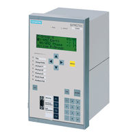
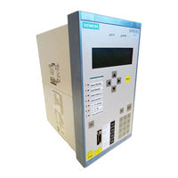
SIPROTEC 6MD63
User Manuals: Siemens SIPROTEC 6MD63 Controller Unit
Manuals and User Guides for Siemens SIPROTEC 6MD63 Controller Unit. We have
2
Siemens SIPROTEC 6MD63 Controller Unit manuals available for free PDF download: Manual, Technical Data Manual
Siemens SIPROTEC 6MD63 Manual (94 pages)
Input/Output unit, Bay control unit, Communication module, PROFIBUS-DP Communication profile
Brand:
Siemens
| Category:
Protection Device
| Size: 0.65 MB
Table of Contents
Preface
3
Revision Index
7
Table of Contents
9
1 PROFIBUS Communication Modules
11
Communication Module Types and Hardware Revisions
12
Communication Module Types
12
Hardware Revisions
12
Compatibility of the Communication Module Hardware with PROFIBUS-DP Firmware Versions and Mapping Files
13
Display of Module-Specific Information at the SIPROTEC Device
15
Block 1: Status and Parameters of the PROFIBUS-DP Slave
17
Block 2: Firmware Versions and Mapping File
19
Block 3: Module Hardware Information and Boot Firmware Version
20
Block 4: OLM Information
21
Block 5: Status of the Event List Via PROFIBUS-DP
24
2 Parameters and Properties
25
Bus Specific Parameters
26
PROFIBUS-DP Settings
26
Configuration of the Fibre-Optical Interface
28
Event List Settings
31
PROFIBUS-DP Configuration Data
31
Execution of Switching Operations Via PROFIBUS-DP
32
Command Output Modes
32
Transformer Tap Change Commands
33
Behaviour under Special Operating Conditions
33
Response in the Event of Disturbed Communication to the PROFIBUS-DP Master
34
Communication Interruption
34
Signalling of Line-Breaks in a Redundant Fibre-Optical Ring
35
Annunciations to the PROFIBUS-DP Master
37
Event List Via PROFIBUS-DP (Sequence of Events Recorder)
38
Properties of the Event List
39
Structure of a PROFIBUS-DP Telegram with Event List
40
Telegram in Input Direction
40
Telegram in Output Direction
42
Handshake Mechanism
43
3 Data Type Definitions
45
Single-Point Indication (SP, Input)
46
Single Command (SC, Output)
47
Double-Point Indication (DP, Input) / Double Command (DC, Output)
48
Measured Value (Signed Integer)
49
Measured Value (Float)
50
Metered Measurand (Unsigned Long)
51
Transformer Tap Change Command (TC)
52
Transformer Tap Position Indication (TM)
53
Message Block for Event List Via PROFIBUS-DP
54
4 PROFIBUS-DP - Parameterization in DIGSI
57
Interface Selection and Mapping Files
58
Standard Mappings 3-1 to 3-N
58
Compatibility with Standard Mappings of Previous Versions
59
Interface Selection and Mapping Selection in DIGSI 4.21
59
Interface Selection and Mapping Selection in DIGSI 4.3 or Higher
63
Customization of the Allocations
66
Scaling of Measured Values
70
Measurement Conversion
70
Number Representation Depending on the Parameterization
71
Parameterization in DIGSI
73
Time Synchronization
75
PROFIBUS-DP Master
75
Parameterization in DIGSI
77
Using SFC14 and SFC15 in STEP7
79
5 Technical Data
83
Connection Via the PSE Module
84
Connection Via the PSO Module
86
Glossary
89
Index
91
Advertisement
Siemens SIPROTEC 6MD63 Technical Data Manual (58 pages)
Multifunction protection with control
Brand:
Siemens
| Category:
Control Unit
| Size: 0.26 MB
Table of Contents
Table of Contents
7
1 Bus Specific Parameters
11
2 Supported Modbus Functions
13
Table 2-1 Supported Modbus Functions
14
3 Exception Responses of the Modbus Slave
15
4 Annunciations to the Modbus Master
17
5 Data Type Definitions
19
Single Command (SC) / Single-Point Indiation (SP)
20
Double Command (DC) / Double-Point Indication (DP)
20
Figure 5-1 Data Typ Single Command / Single-Point Indication
20
Figure 5-2 Data Type Double Command / Double-Point Indication
20
Measured Value (Signed Integer)
21
Metered Measurand (Unsigned Long)
21
Figure 5-3 Data Type Measured Value (Signed Integer)
21
Figure 5-4 Data Type Metered Measurand (Unsigned Integer)
21
6 Modbus Register Map
23
Explanation
23
Notes for Parametrization in DIGSI
24
Coil Status Registers (0X References)
25
Register Addresses 00001 to 00018: Double Commands
25
Register Addresses 00033 to 00054: Single Commands
26
Register Addresses 00065 to 00071: Internal Commands
27
Register Addresses 00081 to 0096: Application Logic CFC
28
Register Addresses 00257 to 00264: Exception Flags
30
Input Status Registers (1X References)
31
Register Addresses 10001 to 10037: Input Channels with Allocation to the Binary Inputs
31
Register Addresses 10049 to 10064: Application Logic CFC
32
Register Addresses 10065 to 10089: Automatic Recloser Status
33
Register Addresses 10097 to 10137: Time Overcurrent Protection
34
Register Addresses 10145 to 10188: Directional Time Overcurrent Protection
35
Register Addresses 10193 to 10200: Unbalanced Load Protection
37
Register Addresses 10209 to 10224: Frequency Protection
37
Register Addresses 10225 to 10247: Undervoltage and Overvoltage Protection
38
Register Addresses 10257 to 10278: Sensitive Ground Fault Protection
39
Register Addresses 10289 to 10298: Circuit Breaker Failure Protection
40
Register Addresses 10305 to 10313: Thermal Overload Protection
40
Register Addresses 10321 to 10325: Motor Start Protection
40
Register Addresses 10337 to 10342: Startup Supervision
41
Register Addresses 10353 to 10359: Trip Coil Monitor
41
Register Addresses 10369 to 10383: Inrush Stabilization
41
Register Address 10385: Fault Locator
42
Register Addresses 10393 to 10396: Cold Load Pickup
42
Register Addresses 10401 to 10408: Measurement Supervision
43
Register Addresses 10417 to 10426: Set Point Alarms
43
Register Addresses 10433 to 10446: Status Annunciations
43
Input Registers (3X References)
45
Reference Values for Selecting a Standard Mapping in Accordance with the Operating Values of the Primary Equipment
45
Recorded Measured Values
46
Holding Registers (4X References)
48
Register Addresses 40001 to 40048: System Information
48
Register Address 40129: Diagnosis
48
Register Addresses 40201 to 40215: Metered Measurands
50
Register Addresses 40251 to 40257: Measured Values - Mean Values
51
Register Addresses 40301 to 40305: Fault Locator and Fault Currents
52
7 Technical Data
53
Modbus Slave for the SIPROTEC Devices
53
Hardware Interface
53
Connection Via the AME Module
54
Connection Via the AMO Module
54
Table 7-1 Technical Data of the Connection Via the AME Module
54
Table 7-2 Assignment of the Bus Connection at the Device (D-SUB Outlet)
54
Table 7-3 Technical Data of the Connection Via the AMO Module
54
8 Glossary
55
9 Index
57
Advertisement
Related Products
Siemens SIPROTEC 6MU805
Siemens 6MD662
Siemens 6MB5110-1
Siemens 6MB5120-1
Siemens 6MB5110-2
Siemens 6MB5120-2
Siemens 6ES7521-1BP00-0AA0
Siemens 6SL3210-1SE26-0AA0
Siemens 6FB1141-1AT11-3WE2
Siemens 6ES7138-7FN00-0AB0
Siemens Categories
Industrial Equipment
Controller
Control Unit
Oven
Washer
More Siemens Manuals
Login
Sign In
OR
Sign in with Facebook
Sign in with Google
Upload manual
Upload from disk
Upload from URL