Sign In
Upload
Manuals
Brands
Siemens Manuals
Controller
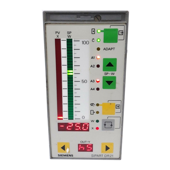
SIPART DR21
Siemens SIPART DR21 Manuals
Manuals and User Guides for Siemens SIPART DR21. We have
1
Siemens SIPART DR21 manual available for free PDF download: Manual
Siemens SIPART DR21 Manual (243 pages)
6DR 210
Brand:
Siemens
| Category:
Controller
| Size: 2.22 MB
Table of Contents
Classification of Safety-Related Notices
3
Controls and Displays
5
Display of Actual Value and Setpoint
5
Modification of Setpoint
5
Block Diagram
6
Table of Contents
7
1 General Part -- Fundamental Control Technology Terms
9
Control Loop
9
Final Control Elements and Actuators
9
Sensors and Transmitters
9
Controllers and Control Response
10
P Controller, Step-Forced Response
10
Step Function
10
Step-Forced Response of P Controller
10
PD Controller, Step-Forced Response
11
PI Controller, Step-Forced Response
11
PID Controller, Step-Forced Response
11
Step-Forced Response of PID Controller
11
Controller Output Signal
12
Function Diagram of Three-Position Step Controller
12
Three-Position Step Controller with Internal Feedback
12
Continuous Controller
13
Function Diagram of Continuous Controller
13
Transient Function / Parameters of the Three-Position Step Controller
13
Function Diagram
14
Switching Ouptupt and Response of Controlled Variable
14
Two-Position Controller
14
Two-Position Controller Without Feedback
14
Long Period
15
Short Period
15
Two-Position Controller with Feedback
15
Safety Notes and Scope of Delivery
17
Scope of Delivery
17
Standard Controllers
17
2 Technical Description
17
Controlling Tasks
18
Range of Application
18
Analog Inputs
19
Features
19
Output Structure
19
Power Supply Unit
20
Slots for Options
20
Voltage Output
20
Blocking Operation
21
Blocking Parameterization and Structuring
21
Blocking Structuring
21
Digital Inputs
21
Computer Operation
22
Computer Standby
22
Digital Outputs
22
Manual Mode
22
Others
23
Backplane Module with Power Supply Unit
24
Design
24
Front Module
24
Standard Controller
24
Connection Technique
25
Front View
25
Rear View
25
Analog Inputs AI1 and AI2
26
Cpu
26
Standard Controller
26
I/U-Module
28
Input for Resistance- or Current Potentiometer
28
Option Module
28
R-Module
28
Reference Point
29
Terminal with Internal Reference Point for Thermocouples
29
UNI-Module
29
2 DI and 4 DO
30
2 DO Relays
30
Measuring Range Plug
30
5 DI
31
Serial Interface PROFIBUS-DP
31
Serial Interface RS 232/RS 485
32
Module with 2 DO-Relays
33
Module with 4 DO-Relays
33
Digital Outputs DO1 and DO2
26
Function Principle
26
Technical Data
34
General Data
34
Installation Position
34
Dimensions SIPART DR21, Dimensions in MM
35
Panel Cut-Outs, Dimensions in MM
35
Power Supply
36
Power Supply Standard Controller
36
Option Module
40
Measuring Range Plug 20 Ma/10 V
42
4Do 24 V, 2Di
43
5Di 24 V
43
Profibus-Dp
43
Coupling Relay 230 V
45
Dimensioned Drawing Coupling Relay, Dimensions in MM
46
Analog Input Signal Processing (S3 to S21)
47
3 Functional Description of the Structure Switches
47
General
47
Analog Input Signal Processing
49
Assignment and Direction of Effect of the Digital Inputs
50
Digital Input Signal Processing (S23 to S41)
50
Assignment and Direction of Action of the Digital Inputs S23 to S40
52
Functional Explanation of the Control Signals
54
Controller Types (S1, S42 to S45)
55
General, Recurrent Functions
55
Setpoint Preset Wi or Nominal Ratio Preset Wvi by the SES
55
Source for the External Setpoint (S85)
55
Setpoint Switching with Ramp
56
Setpoint Limits SA, SE
56
Tracking of the Ineffective Setpoint to the Active Setpoint
56
X-Tracking (S43)
56
Constants C1 to C7
57
Control Signals for the Setpoint Switching
57
Actual Value- and Setpoint Display
58
Display Range
58
Y-Display
59
Control Principle S1 = 0
59
Fixed Setpoint Controller with 2 Independent Setpoints (S1 = 0)
59
Switching between Wi1 and Wi2
60
Display Levels (S81)
60
Slave Controller, Synchronized Controller, SPC-Controller
62
Control Principle S1 = 1
62
SPC-Controls
63
Cascade Controls
63
Slave Controls
63
Display of the External Setpoint W
64
Operation with 2 or 3 Setpoints
64
Controlled Variable Processing
64
DDC-Fixed Setpoint Controller (S1 = 2)
68
Control Principle S1 = 2
68
DDC-Control Unit
69
Display Levels
73
Block Diagram S1 = 2, DDC Fixed Setpoint Controller
74
Controlled Ratio Controller (S1 = 3)
75
Example of a Ratio Control
78
Control Diagram Ratio Control
78
Control Unit/Process Display (S1 = 4)
80
Display of Gas-/Air Ratio in Controlled Status
80
Control Units
83
Setpoint Generator
83
Fixed Setpoint Controller with One Setpoint (Control System Coupling)
89
Slave Controller Without Int/Ext -Switching (Control System Coupling)
90
Control Algorithm
91
Controller Direction of Effect
91
Block Diagram Controller Structure
92
Automatic Working Point (Yo = Auto)
93
Fixed Working Point (Yo = 0 to 100 %)
93
Manipulated Variable Limit YA, YE
93
Operating Point Yo for P-Controllers
93
Bumpless Switching to Automatic Mode
94
Controller Output Structures (S2, S49 to S55)
94
K-Controller
94
P-PI-Switching
94
Setting Ratio, Actuating Pulses of Two-Position Controller
98
Three-Position Step Controller (S) with Internal Feedback
99
Three-Position Step Controller (S) with External Feedback
102
Automatic Mode
107
Safety Operation
107
Tracking-(DDC)-Operation
107
Blocking of the Manual/Automatic Switching (S51)
108
Direction-Dependent Blocking Operation
108
Manual Mode in the Case of a Transmitter Fault (S50)
108
Source and Direction of Effect of the Y-Display (S54, S55)
108
Control System Coupling Via the Serial Interface
109
Analog Output Iy Assignment and Current Range
110
Analog Output Signal Processing (S56)
110
Digital Output Signal Processing (S57 to S75)
111
Functional Explanation of the Digital Message Signals
111
No Computer Standby of the Controller
111
Assignment of Digital Outputs (S57 to S75)
112
Adaptation (S48)
113
System Identification
113
Controller Design
114
Other Functions of the Standard Controller
115
3.10.1 Adaptive Filter
115
Effect of the Adaptive Non-Linear Filter
116
Effect of the Dead Zone Element
116
3.10.2 Response Threshold AH
116
Limit Value Alarm (S76 to S80)
117
Display Format of the Limit Values A1 to A4
117
Assignment and Function of the Limit Value Alarms (S76 to S79)
118
Linearizer (S21, Ofpa)
118
Restart Conditions (S82, S83)
120
Serial Interface and PROFIBUS-DP (S84 to S91)
120
Mechanical Installation
121
Work Prior to Installation
121
Selecting the Installation Site
121
Switching Mains 230 V to 115 V
122
Setting the Mains Voltage
122
Unlock the Relay Contacts
122
Relay Contact Locking
123
Changing the Tag Plate and Scales
123
Tag Plate
123
Installing the Controller
124
Panel Mounting
124
Procedure / Removing the Front Module
124
Installation of the Options Modules
125
Jumper Settings
125
Rear of Controller
125
Electrical Connection
126
Warnings and Block Diagram
126
PE Conductor Connection
126
Power Supply Connection
126
Connection of Measuring- and Signal Lines
127
Zero-Volt-System
128
Block Diagram SIPART DR21
129
Connection Standard Controller
130
Connection 115/230 V AC Power Supply
130
Connection 24 V UC Power Supply
130
Connection of Measuring- and Signal Lines AI1 and AI2
131
Wiring AI1 to AI2, Current Inputs
131
Connection DI1 to DI2
131
Connection AO
131
Connection DO1 to DO2
132
Connection L+
132
Connection of the Options Modules
133
Connection U/I-Module 6DR2800-8J
133
4.2.3.1 Modules for Analog Measuring Inputs
133
Connection R-Module 6DR2800-8R
134
Connection UNI-Module AE3 S8=0
135
Connection UNI-Module AE3 S8=0 with Measuring Range Plug
135
Connection UNI-Module AI3 S8 = 1, 2
136
Connection UNI-Module AI3 S8 = 3, 4, 5
136
Connection UNI-Module AI3 S8 = 6, 7
137
Connection Examples for Analog Measuring Inputs with the Module 6DR2800-8J
137
D Voltages 0/0.2 to 1 V or 0/2 to 10 V
140
Connection of a Floating Voltage Supply
140
Double-Pin Wiring of a Voltage Source with Negative Polarity to Ground
141
Wiring of 5DI Module 6DR2801-8C
142
Connection of 4DO (24 V)-Module 6DR2801-8E
142
4.2.3.3 Modules for Expanding the Digital Inputs and Digital Outputs
142
2DO Relay 35 V
143
Connection of 2DO (Relay) -Module 6DR2801-8D
143
Connection of Coupling Relay 230 V 6DR2804-8B
143
Connection of the Interface Module 6DR2803-8C
144
RS 232 Point-To-Point (END/END)
144
Jumper Settings SES-Module 6DR2803-8C in RS 485 Bus
145
RS 485-Bus Connection
145
4.2.4.2 RS 485 Bus
145
4.2.4.3 Profibus-Dp, 6Dr2803-8P
146
Connecting the Interface PROFIBUS-DP, 6DR2803-8P
147
Block Diagram SIPART DR21 Via PROFIBUS-DP and Bus Plug to Master
147
Blocking, Operation
149
General
149
Operating Locks
149
Operating Modes
149
5 Operation
149
Sipart Dr21
149
Actual Value
150
Behavior of the Controller in the Factory Setting
150
Control Elements
150
Process Operation Mode
150
Adaptation
151
Alarms
151
Display of the Software Version
151
Lamp Test
151
Control and Display Elements in the Selection Mode
152
Selection Mode
152
Overview Selection Mode
153
Configuration Modes
154
General, Online and Offline Modes
154
Configuration Mode Online-Parameters Onpa
155
Online Parameter List
155
Configuration Mode Adaptation Adap
156
Control and Display Elements in the Configuration Mode Onpa
156
Conditions for Adaptation
157
Pre Adaptation
157
During Adaptation
157
Aborted Adaptation
157
Overview Configuration Level Adap
159
Post Adaptation
160
Control and Display Elements in the Configuration Mode Adap
160
List of Start Parameters
161
Parameter List Adap
161
Error Messages of the Adaptation Procedure
162
Configuration Level Offline Parameters Ofpa
163
Control and Display Elements in the Parameterization Mode Ofpa
163
Offline Parameter List
164
Configuration Mode Structure Switch Strs
165
Control and Display Elements in the Configuration Mode Strs
165
Strs -- Structure Switch List
166
Set UNI-Module CAE3
173
Calling, Setting and Leaving the CAE3 Menu
174
CAE3-Menu Parameter List
174
MA/ME – Set Measuring Range
175
CA/CE – Fine Adjustment
175
Measuring Range for MV (S8 = 0)
175
Measuring Range for U, I (S8 = 0)
175
Measuring Range for Thermocouple with Internal Reference Point (S8 = 1)
175
D Tb – External Reference Points-Temperature
176
Measuring Range for Thermocouple with External Reference Point (S8 = 2)
176
Measuring Range for PT100 Four-Wire and Three-Wire Connection (S8 = 3,4)
176
Measuring Range for PT100 Two-Wire Connection (S8 = 5)
177
MR/CR Adjustment of the Feed Line Resistance
177
Measuring Range for Resistance Potentiometer (S8 = 6, 7)
177
Apst (All Preset) Reset to Factory Setting
178
Control and Display Elements in the Structuring Mode Apst
178
CPU Self-Diagnostics
179
Error Message of the CPU
179
Power On-Reset
179
Watch_Dog Reset
179
Adapting the Direction of Control Action to the Controlled System
181
6 Commissioning
181
Definitions
181
Normal Control Action System
181
Normal Effecting Actuator (Valve)
181
Determine Direction of Control Action of the Final Control Element
182
Determine the Direction of Control Action of the System
182
Direction of Control Action of System / Final Control Element Unknown
182
S-Controller
182
Adaptation of the S-Controller to the Actuating Drive
183
S-Controller with Internal Feedback
183
Setting of Actuating Time in K-Controllers (S2 = 0)
183
Adaptive, Non-Linear Filters of the Control Difference
185
Filter of First Order of Analog Inputs
185
Optimization of the Response Threshold AH
185
Setting the Filter and the Response Threshold
185
Automatic Setting of Control Parameters by the Adaptation Method
186
Notes on the Adaptation Results
186
S48 Selecting the Control Behavior (Structuring Mode Strs)
186
Tu: Monitoring Time (Parameterization Mode Adap)
186
Kp Variation
187
Manual Setting of the Control Parameters Without Knowledge of the Plant Behavior
189
P-Controller (Control Signal P = High)
189
PD-Controller (Control Signal P = High)
189
PI-Controller
190
PID-Controller
190
Manual Setting of the Control Parameters after the Transient Function
191
Transient Function of a Controlled System with Compensation
191
7 Application Examples for Configuring the Controller
193
General
193
Input Circuits
193
Mains Voltage
193
Output Circuits
193
Structure Switches S
194
Setpoint Curve According to Example 1
195
Working with Different Setpoints
195
Setpoint Curve According to Example 2
196
Setpoint Curve According to Example 3
197
Switchings Take Place
197
Setpoint Curve According to Example 4
198
Configuration Examples
199
Configuring Tool, Forms
216
K/S-Controller 6DR2100-4/-5
217
General Information and Handling
223
8 Maintenance
223
Exchanging Components
224
Front Module with Removed Tag Plate Cover
224
Replacing the Front Module
224
Controller Rear View
225
Replacement of the Backplane Module
225
Replacing the Options Modules
225
Backplane Module
226
Disconnect the Power Supply Unit from the Basic Circuit Board
226
LED-Test and Software Version
226
Spare Parts List
227
Ordering Data
228
9 General Explanation of Abbreviations for SIPART DR
229
Index
235
Advertisement
Advertisement
Related Products
Siemens SIPART DR20
Siemens SIPART DR19
Siemens SIPART DR22
Siemens SIPART DR24
Siemens SIMOTION D410-2DP/PN
Siemens SIMATIC NET CP 1243-1 DNP3
Siemens SIMOTION D410
Siemens DESIGO PX Series
Siemens DE406M Series
Siemens SIPART PS2
Siemens Categories
Industrial Equipment
Controller
Control Unit
Oven
Washer
More Siemens Manuals
Login
Sign In
OR
Sign in with Facebook
Sign in with Google
Upload manual
Upload from disk
Upload from URL