Sign In
Upload
Manuals
Brands
Siemens Manuals
Control Unit
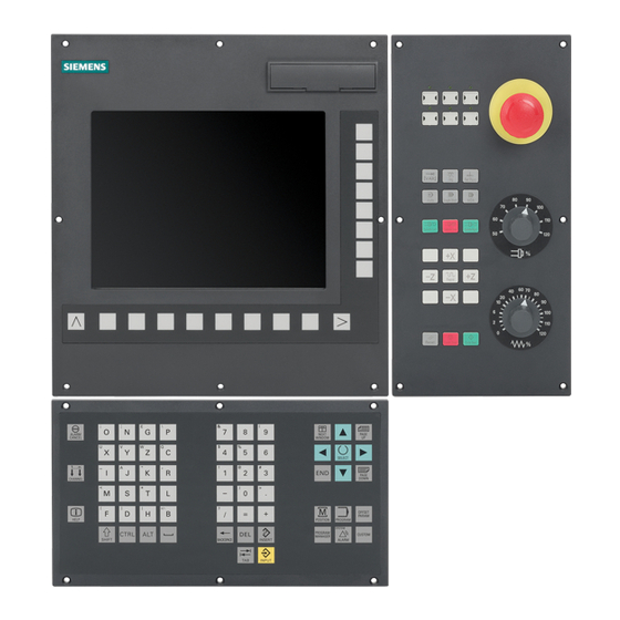
SINUMERIK 802D
Siemens SINUMERIK 802D Manuals
Manuals and User Guides for Siemens SINUMERIK 802D. We have
3
Siemens SINUMERIK 802D manuals available for free PDF download: Programming And Operating Manual, Training Manual, Short Manual
Siemens SINUMERIK 802D Programming And Operating Manual (399 pages)
Brand:
Siemens
| Category:
Control Unit
| Size: 12.19 MB
Table of Contents
Preface
3
Table of Contents
7
1 Description
13
Control and Display Elements
13
Key Definition of the Full CNC Keyboard (Vertical Format)
15
Key Definition of the Machine Control Panel
17
Coordinate Systems
19
2 Software Interface
23
Screen Layout
23
Standard Softkeys
27
Operating Areas
28
The Help System
30
3 Turning On, Reference Point Approach
33
Turning on and Reference Point Approach
33
4 Define
35
Entering Tools and Tool Offsets
35
Create New Tool
37
Sense Dresser
46
Sense Workpiece
48
Shaping/Dressing
50
Sense Probe
52
Manual Grinding
54
Program Setting Data
58
Arithmetic Parameter R
62
User Data
63
5 Manual Mode
65
JOG Mode - "Position" Operating Area
66
Assigning Handwheels
69
MDA Mode (Manual Input) "Position" Operating Area
70
Teach in (MDA)
73
6 Automatic Mode
77
Machining Offset
83
Selection and Start of a Part Program
84
Block Search
86
Simultaneous Recording
89
Stop / Cancel a Part Program
92
Reapproach after Cancellation
93
Repositioning after Interruption
94
Execute from External
95
7 Part Programming
99
Part Programming Overview
99
Enter New Program
103
Editing the Part Program
104
8 System
107
System" Operating Area
107
SYSTEM - "Start-Up" Softkeys
112
SYSTEM - "Machine Data" Softkeys
113
SYSTEM - "Service Display
120
Action Log
122
Servo Trace
123
Version/Hmi Details
127
Service MSG
131
SYSTEM - "PLC" Softkeys
137
SYSTEM - "Start-Up Files" Softkeys
145
Alarm Display
150
9 Cycles
153
Overview of Cycles
153
Programming Cycles
155
Call and Return Conditions
155
Error Messages and Error Handling
156
General Information
156
Error Handling Within Cycles
156
Cycle Call and Parameter List
157
Special Characteristics of Grinding Cycles
158
Zyklenunterstützung IM Programmeditor
161
Taper Grinding - CYCLE405
164
Z Positioning with Grinding Wheel - CYCLE406
167
Obstacle Diameter - CYCLE407
169
Plunge-Cutting - CYCLE410
170
Multiple Plunge-Cutting - CYCLE411
175
Shoulder Plunge-Cutting - CYCLE412
181
Oblique Plunge-Cutting - CYCLE413
185
Radius Grinding - CYCLE414
190
Reciprocating - CYCLE415
194
Dressing and Profiling - CYCLE416
200
General Workpiece Data - CYCLE420
203
Dressing with Profile Roller - CYCLE430
207
Selection of the Grinding Wheel Peripheral Speed - CYCLE446
209
Technological Data - CYCLE450
210
Oblique Plunge-Cutting with Z Allowance - CYCLE451
211
Longitudinal Surface Grinding - CYCLE452
215
10 Programming
219
Fundamental Principles of NC Programming
219
Program Names
219
Program Structure
220
Word Structure and Address
221
Block Format
222
Character Set
224
Overview of the Instructions - Grinding
225
Positional Data
238
Programming Dimensions
238
Absolute / Incremental Dimensioning: G90, G91, AC, IC
239
Dimensions in Metric Units and Inches: G71, G70, G710, G700
241
Radius / Diameter Dimensions: DIAMOF, DIAMON, DIAM90
242
Programmable Work Offset: TRANS, ATRANS
244
Programmable Scaling Factor: SCALE, ASCALE
245
Programmable Mirroring (MIRROR, AMIRROR)
247
Programmable Mirroring (MIRROR, AMIRROR)_2
248
Settable Zero Offset: G54 to G59, G507 to G512, G500, G53, G153
250
Programmable Working Area Limitation: G25, G26, WALIMON, WALIMOF
251
Axis Movements
253
Linear Interpolation with Rapid Traverse: G0
253
Linear Interpolation with Feedrate: G1
255
Circular Interpolation: G2, G3
256
Circular Interpolation Via Intermediate Point: CIP
260
Circle with Tangential Transition: CT
261
Fixed Point Approach: G75
261
Reference Point Approach: G74
263
Measuring with Touch-Trigger Probe: MEAS, MEAW
263
Feedrate F
265
Exact Stop / Continuous-Path Control Mode: G9, G60, G64
266
Acceleration Pattern: BRISK, SOFT
269
Percentage Acceleration Override: ACC
270
Traversing with Feedforward Control: FFWON, FFWOF
271
And 4Th Axis
272
Dwell Time: G4
273
Travel to Fixed Stop
274
Spindle Movements
278
Spindle Speed S, Directions of Rotation
278
Spindle Speed Limitation: G25, G26
279
Spindle Positioning: SPOS
280
Gear Stages
281
Spindle
281
Special Functions
283
Constant Cutting Rate: G96, G97
283
Rounding, Chamfer
285
Tool and Tool Offset
288
General Information
288
Tool T
288
Tool Offset Number D
289
Selecting the Tool Radius Compensation: G41, G42
292
Corner Behavior: G450, G451
295
Tool Radius Compensation OFF: G40
296
Special Cases of the Tool Radius Compensation
297
Example of Tool Radius Compensation
298
Special Handling of Tool Compensation (Grinding)
299
Miscellaneous Function M
301
H Function
303
Arithmetic Parameters, LUD and PLC Variables
304
Arithmetic Parameter R
304
Local User Data (LUD)
306
Reading and Writing PLC Variables
308
Program Jumps
309
Jump Destination for Program Jumps
309
Unconditional Program Jumps
310
Conditional Program Jumps
311
Program Example for Jumps
313
Subroutine Technique
315
General Information
315
Calling Machining Cycles
318
Timers and Workpiece Counters
319
Runtime Timer
319
Workpiece Counter
321
Inclined Axis
323
Inclined Axis (TRAANG)
323
Inclined Axis (TRAANG)_2
325
Inclined Axis Programming (G05, G07)
326
Multiple Feedrate Values in One Block
328
Oscillation
330
11 Network Operation
335
Network Operation Prerequisites
335
RCS802 Tool
336
Network Operation
341
Configuring the Network Connection
342
User Management
344
User Log in - RCS Log in
345
Working on the Basis of a Network Connection
346
Sharing Directories
347
Connecting / Disconnecting Network Drives
348
12 Data Backup
351
Data Transfer Via RS232 Interface
351
Creating / Reading in / Reading out a Start-Up Archive
353
Reading in / Reading out PLC Projects
356
Copying and Pasting Files
357
13 PLC Diagnostics
359
Screen Layout
360
Operating Options
361
14 Application Examples
373
Cycle Example 1
373
Cycle Example 2
375
Appendix
377
User Data
377
A.1 User Data
377
Parameter Tables of the Tool Data
380
Miscellaneous
385
Pocket Calculator
385
A.3 Miscellaneous
385
Editing Asian Characters
387
Feedback on the Documentation
391
Overview
393
A.5 Overview
393
Glossary
395
Index
397
Advertisement
Siemens SINUMERIK 802D Training Manual (213 pages)
Brand:
Siemens
| Category:
Control Unit
| Size: 18.97 MB
Table of Contents
CNC Basic Principles Milling
7
Brief Description
7
Module Content
7
Fundamentals of CNC Machines
7
Basic Program Structure
9
Basic Structure of NC Program
10
Basic Structure of NC Program for Turning
11
Basic Structure of NC Program for Milling
12
Modality (Preparatory Functions)
13
G Function Overview
14
Modally Valid Motion Commands
15
Non-Modally Valid Motion, Dwell
15
Programmable Frame, Working Area Limitation
15
Plane Selection
15
Tool Radius Compensation
16
Settable Zero Offset
16
Frame Suppression
16
Exact Stop - Continuous-Path Mode
16
Workpiece Measuring Inch/Metric
17
Workpiece Measuring Absolute/Incremental
17
Feed Type
17
Feed Override on Inside and Outside Curvature
17
G Function Window Display
18
Commonly Used G Functions Milling
21
G Functions “Milling” in Detail
22
Linear Interpolation G01
22
Circular Interpolation, G02/G03
22
Dwell Time G4
23
Plane Selection G17
23
Tool Radius Compensation G40
24
Tool Radius Compensation G41
24
Tool Radius Compensation G42
24
Zero Offset G54 to G59
25
Absolute Dimension G90
25
Feed Rate G94
26
Feed Rate G95
26
Exact Stop/Continuous-Path Control: G09, G60, G64
26
Example Contour Program
27
Example Drilling Program
29
Miscellaneous Codes
31
Tool Offset Number D
32
Path Velocity F
33
Spindle Speed S
33
Miscellaneous Functions
34
Program Stop (M00, M01)
34
End of Program, M02, M17, M30
35
Direction of Spindle Rotation (M03 - M04 - M05)
35
Tool Change (M06)
35
Coolant ON/OFF (M08 - M09)
36
T, D, F, S Window Display
37
M and H Window Display
38
Additional G Functions for Milling
39
Additional G Functions in more Detail
40
Rounding, Chamfer - RND, CHF, CHR
40
Angle - ANG
40
Unconditional Program Jumps
41
Conditional Program Jumps
41
Milling on Peripheral Surface - TRACYL
42
Creation of a Milling Program
45
Creating a Work Plan
46
Creating a List of Tools
47
Define the Program Structure
48
End Mill D60Mm
48
Slot Mill D6Mm
48
Create Example Program in Editor
49
Simulate the Program
51
Testing with Simulation
51
Sequence of Operation for Simulation
51
Cycles for Milling
53
Graphical Cycles Support
54
Drilling Cycles
62
Drilling, Centering - CYCLE82
64
Working with CF Cards
71
Brief Description
71
Copying Data to and from the Card
72
Power on and Referencing
75
Switch on the Control
76
Referencing the Axis
77
Axis Control / Jog
79
Jog
80
Jog 1 INC, 10 INC, 100 INC, 1000 INC
81
Jog VAR
82
Control Structure and Navigation
91
Overview of Operating Areas
92
Functionality of the Operating Areas
93
Overview of the Softkeys in JOG
93
Overview of the Softkeys in MDA
93
Overview of the Softkeys in AUTOMATIC
94
Overview of the Softkeys in PROGRAM
94
MDA Milling
95
Functionality of MDA
96
Example Program for MDA
96
Save MDA to Program
97
Face Milling
98
Tools Turning / Milling Functions
101
Working Plane Selection
102
Tool Types for Milling/Drilling G17 Plane
106
Tool Types for Milling G17 & G19 Plane
111
Milling Tool and Workplanes
113
Tool Geometry and Workplanes
114
Tool Offset for Milling Tools
115
New Milling Tool
116
Tool Setting on the Machine
117
Measuring Mode Selection
118
Drilling Tools
119
Work Offsets Milling
121
Overview of the Coordinate System
122
Description of the Zero Offset
122
Description of the Single Components
122
Machine Coordinate System (MCS)
122
Basic Coordinate System (BCS)
123
Wokpiece Coordinate System (WCS)
123
Zero Offset Page in the Control
125
Setting the Zero Offset
127
Automatic
129
Select Part Program
130
Starting a Program
132
RCS802 Data Transfer Tool
133
Principle of Operation RCS802
134
RS232C Online Connection
134
Configure Interface on the Control
135
ISO Dialect Programming for Milling
139
Introduction to ISO Dialect
140
Siemens Mode
140
ISO Dialect Mode
140
Switch over
141
ISO Dialect Milling Addresses
143
Milling G Codes
144
Tool Length Offset (G43, G44, G49)
145
Return Value (G98, G99)
145
Advanced Level Commands
146
Canned Cycles (G73 to G89)
146
Subprogram Call up Function (M98, M99)
147
Basic ISO Dialect Program
148
Mold & die Functionality and Programming
149
List of G Codes
151
Recommended Function
151
Preprocessing Memory Control
151
Soft Smoothed Path Acceleration
152
Feed Forward Control on
153
Recommended Function : COMPCAD
154
Freeform Surface
155
Transfer and Copy a Program
156
Edit a Program
157
Execute a Program
158
Program Roughing
159
Program Header
159
Program Finishing
160
LED Diagnosis HMI
161
Locating the Status Led's
162
Status of CNC Controller Led's
162
MCPA Signal Tests
163
Identification of MCPA in the System
164
Analogue Spindle Interface Test
164
Save Data
165
Performing a Data Save
165
Performing a Save Data
166
Restore Saved Data
169
External Data Backup + Restore with CF Card
171
Saving All Data to Compact Flash Card
172
Restoring All Data from Compact Flash Card
175
Diagnose PLC Program
179
Locating the PLC Program Displays
180
Navigating the Displays
181
Navigating the Displays
182
Program Status ON/OFF
184
Searching
185
Cross Referencing
185
Diagnose PLC Alarm
187
Structure of an Alarm
188
Variable Definition
188
Function of Alarm
189
Cross Reference
190
Alarm Structure NC
191
Locate the Alarm Display
192
Editing of NC Machine Data
193
Location of NC Machine Data
194
Setting Password
195
Changing Machine Data + Data Save
195
Drive Diagnostic Parameters
197
Location of Drive Diagnostic Parameters
198
Pushbutton Tests
201
Hardware Identification
202
Identification of MCP Connected to MCPA Interface Module
202
Identification of MCP Connected to PLC Periphery Board
203
General Information Regarding the Machine Control Panel
204
Hardware Interface
204
Hardware Interface—Mcp Pushbutton Test with Periphery Version
205
Hardware Interface - MCP Pushbutton Test with MCPA Version
207
LED Diagnosis—Drive
209
MM Led's, ALM Led´s, SLM Led´s ≥ 16Kw
210
Siemens SINUMERIK 802D Short Manual (49 pages)
Milling ISO Dialect
Brand:
Siemens
| Category:
Control Systems
| Size: 0.26 MB
Table of Contents
Table of Contents
6
1 Setup
10
Activate ISO Dialect M, G291
10
Tool Offsets
11
Enter Zero Offset
12
2 Create/Edit Program
13
Create/Open Program
14
Insert/Edit Block
15
Copy/Insert/Delete Block
16
Block Search/Numbering
17
Start/Simulate Program
18
3 Execute/Correct Program
19
Select/Trace Program
20
Correct Program
21
Block Search
22
4 Program Positional Data
24
Zero Offset, G54 to G59
25
Select the Working Plane, G17 to G19
26
5 Program Axis Motions
27
Rapid Traverse, G0
28
Linear Interpolation, G1
29
Circular Interpolation, G2/G3
30
Tapping, G74/G84
31
Polar Coordinates, G15/G16
32
6 Tool Offsets
33
Call Tool
33
Cutter Radius Path Offset, G41/G42
33
7 Program Preparatory Functions
37
Feed in Continuous-Path Mode, G64
40
Program Spindle Motion
41
8 Appendix
43
List of M Commands
44
List of the G Functions
45
Cycle Alarms
47
Notes
48
Advertisement
Advertisement
Related Products
Siemens SINUMERIK 805
Siemens SINUMERIK 804D sl
Siemens Sinumerik 840CE
Siemens SINUMERIK 880 SW 6
Siemens SINUMERIK 880 GA2
Siemens SINUMERIK 880 GA2 T/M
Siemens SINUMERIK 828D 24x.3 BASIC PPU Series
Siemens SINUMERIK 828D 26x.3 PPU Series
Siemens SINUMERIK 840D 7.4
Siemens SINUMERIK 840DE 7.4
Siemens Categories
Industrial Equipment
Controller
Control Unit
Oven
Washer
More Siemens Manuals
Login
Sign In
OR
Sign in with Facebook
Sign in with Google
Upload manual
Upload from disk
Upload from URL