Sign In
Upload
Manuals
Brands
Siemens Manuals
Controller
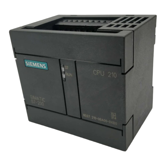
Simatic S7-200 CPU 210
Siemens Simatic S7-200 CPU 210 Manuals
Manuals and User Guides for Siemens Simatic S7-200 CPU 210. We have
1
Siemens Simatic S7-200 CPU 210 manual available for free PDF download: System Manual
Siemens Simatic S7-200 CPU 210 System Manual (140 pages)
Brand:
Siemens
| Category:
Controller
| Size: 0.78 MB
Table of Contents
Table of Contents
5
1 Installing the S7-200 CPU 210
11
Product Overview
12
Equipment Requirements
12
Features of the CPU 210
13
Pre-Installation Considerations
14
Installation Configuration
14
Clearance Requirements for Installing a CPU 210
14
DIN Rail Requirements
15
Panel-Mounting Dimensions
15
Installing a CPU 210
16
Mounting a CPU 210 on a Panel
16
Installing a CPU 210 in a Panel Box
17
Installing the Field Wiring
18
General Guidelines
18
Grounding and Circuit Referencing Guidelines for Using Isolated Circuits
19
Using the Optional Field Wiring Connector
20
Guidelines for AC Installation
20
Guidelines for DC Installation
20
Using Suppression Circuits
22
Protecting DC Transistors
22
Protecting Relays Controlling DC Power
22
2 Installing and Using the STEP 7-Micro/Win Version 2.0 Software
23
Installing the STEP 7-Micro/Win Version 2.0 Software
24
Pre-Installation Instructions
24
Installation Instructions for Windows 3.1
24
Installation Instructions for Windows 95
24
Troubleshooting the Installation
24
Establishing Communication with the PDS 210
25
Connecting Your Computer to the PDS 210 for PPI Communications
25
Setting up the Communications Parameters
26
Configuring the Preferences for STEP 7-Micro/Win
27
Creating and Saving a Project
28
Creating a New Project
28
Saving a Project
28
Creating a Program
29
Entering Your Program in Ladder
29
Entering Your Program in Statement List
30
Compiling the Program
30
Viewing a Program in Ladder or Statement List
31
Downloading a Program
32
Downloading the Program to the PDS 210
32
Copying Your Program to the Memory Cartridge
33
Transporting the Program to the CPU
33
Using Symbolic Addressing
35
Guidelines for Entering Symbolic Addresses
35
Starting the Symbol Table Editor
35
Editing Functions Within the Symbol Table
36
Sorting Table Entries
36
Displaying the Symbolic Addresses
36
Using the Status Chart
37
Reading and Writing Variables with the Status Chart
37
Editing Addresses
37
Debugging and Monitoring Your Program
38
Using Single/Multiple Scans to Monitor Your Program
38
Displaying the Status of the Program in Ladder Logic
38
Error Handling for the PDS 210
39
Responding to Fatal Errors
39
Responding to Non-Fatal Errors
40
3 Getting Started with a Sample Program
41
Defining the Requirements for the Application Example
42
Defining the Inputs and Outputs for the Application
42
Creating Symbolic Names for the Elements of the Program
42
Designing the Control Logic
44
Defining the Operation of the Program
44
Designing the Control Logic for Arming and Disarming the System
46
Designing the Control Logic for Turning on the Low-Level Alert Notification
47
Designing the Control Logic for Turning on the Alarm and Modem Dialer
48
Putting the Control Logic into a Program
49
Creating a Project with STEP 7-Micro/Win
53
Creating a Symbol Table
54
Entering the Symbol Names
54
Entering the Program
55
Programming with Symbolic Addresses
55
Using the Ladder Editor to Enter the Program
55
Compiling the Program
61
Saving the Sample Program
61
Creating a Status Chart
62
Building a Status Chart
62
Downloading and Monitoring the Sample Program
63
Downloading the Project to the PDS 210
63
Using the Ladder Editor to Monitor the Status of the Program
63
Using the Status Chart to Monitor and Modify the Current Values of the Program
64
Modifying the Sample Program
65
Creating the Blink Patterns for the LED
65
Turning the LED on and off
66
4 Basic Concepts for Programming the CPU 210
70
Guidelines for Designing a Micro PLC System
70
Partitioning Your Process or Machine
70
Creating the Functional Specifications
70
Designing the Safety Circuits
71
Specifying the Operator Stations
71
Creating the PLC Configuration Drawings
71
Creating a List of Symbolic Names
71
Concepts for Creating a Program
72
Relating the Program to Inputs and Outputs
72
Accessing Data in the Memory Areas
72
Organizing the Program
73
Understanding the Scan Cycle of the CPU
74
Understanding the Basic Scan Cycle of the CPU 210
74
Understanding the Basic Scan Cycle of the PDS 210
75
Using the Debug Option to Specify the Number of Scans
76
Understanding the Programming Languages
77
Understanding the Basic Elements of Ladder
77
Understanding the Statement List Instructions
78
Understanding the Addresses of the Memory Areas
79
Using the Memory Address to Access Data
79
Addressing the Input Image Register (I)
80
Addressing the Outputs (Q)
80
Addressing the Bit Memory (M) Area
80
Addressing the Special Memory (SM) Bits
80
Addressing the Timer (T) Memory Area
81
Addressing the Counter (C) Memory Area
81
Using Constant Values
81
Sample Program Using an Interrupt Routine
82
Using the Analog Adjustment Potentiometer
84
5 Instruction Set
85
Valid Ranges for the CPU 210 and PDS 210
86
Valid Operand Ranges
86
Contact Instructions
87
Standard Contacts
87
Not
87
Positive, Negative Transition
87
Compare Word Integer
88
Contact Examples
88
Output
89
Set, Reset
89
Output Example
89
Timer Instructions
90
On-Delay Timer
90
Understanding How the CPU 210 Updates the Timers
90
Timer Example
91
Counter Instructions
92
Up/Down Counter
92
Counter Example
92
Increment and Decrement Instructions
93
Increment Word, Decrement Word
93
Increment, Decrement Example
93
Move Instruction
94
Move Word
94
Move Examples
94
Program Control Instructions
95
End
95
Watchdog Reset
95
Considerations for Using the WDR Instruction to Reset the Watchdog Timer
95
END and WDR Example
96
Jump to Label, Label
96
Jump to Label Example
96
Logic Stack Instructions
97
And Load
97
Or Load
97
Logic Stack Example
97
5.10 Interrupt Instructions
98
Interrupt Routine, Return from Interrupt Routine
98
Enable Interrupt, Disable Interrupt
98
Guidelines and Restrictions for Using the Interrupt Routine
99
Sharing Data between the Main Program and the Interrupt Routine
99
Interrupt Example
100
ACPU 210 Data Sheets
102
General Technical Specifications
102
CPU 210 DC Power Supply, 24 VDC Inputs, 24 VDC Outputs
104
CPU 210 AC Power Supply, 24 VDC Inputs, Relay Outputs
106
CPU 210 AC Power Supply, AC Inputs, Relay Outputs
108
PDS 210 AC Power Supply, DC Inputs, Relay Outputs
110
Memory Cartridge 8K X
112
Memory Cartridge 16K
112
A.6 Memory Cartridge 8K X 8
112
A.7 Memory Cartridge 16K X 8
113
PC/PPI Cable
114
A.8 PC/PPI Cable
114
A.9 DC Input Simulator
115
DC Input Simulator
115
DC Input Simulator
125
Programmable Controller CPU
125
Index Index
129
Advertisement
Advertisement
Related Products
Siemens S7-1200 TELECONTROL
Siemens Simatic S7-1500
Siemens Simatic S7-1500R
Siemens Simatic S7-1500H
Siemens SIMATIC S7-1500T
Siemens SIMATIC S7-400H
Siemens SIMATIC S7 F
Siemens SIMATIC S7 FH
Siemens S7 Series
Siemens SITRANS S7-400 PLC
Siemens Categories
Industrial Equipment
Controller
Control Unit
Oven
Washer
More Siemens Manuals
Login
Sign In
OR
Sign in with Facebook
Sign in with Google
Upload manual
Upload from disk
Upload from URL