Sign In
Upload
Manuals
Brands
Siemens Manuals
Rfid Systems
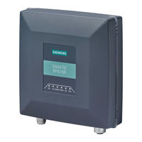
SIMATIC RF615R
Siemens SIMATIC RF615R Manuals
Manuals and User Guides for Siemens SIMATIC RF615R. We have
4
Siemens SIMATIC RF615R manuals available for free PDF download: System Manual, Configuration Manual, Getting Started
Siemens SIMATIC RF615R System Manual (490 pages)
Brand:
Siemens
| Category:
Rfid Systems
| Size: 5.81 MB
Table of Contents
Table of Contents
3
1 Introduction
13
Preface
13
Abbreviations and Naming Conventions
14
2 Safety Information
15
General Safety Instructions
15
Safety Instructions for Third-Party Antennas as Well as for Modifications to the RF600 System
19
Safety Distance to Transmitter Antenna
20
Safety Distance between Transmitter Antenna and Personnel
20
Minimum Distance to Antenna in Accordance with ETSI
21
Minimum Distance to Antenna in Accordance with FCC (USA)
22
3 System Overview of SIMATIC RF600
25
Application Areas of RF600
26
System Components
27
Features
30
4 RF600 System Planning
33
Overview
33
Possible System Configurations
33
Intralogistics Scenario
34
Scenario for Workpiece Identification
36
Goods Tracking Scenario
37
Scenario Incoming Goods, Distribution of Goods and Outgoing Goods
38
Antenna Configurations
39
Antenna Configuration Example
40
Possibilities and Application Areas for Antenna Configurations
41
Transponder Orientation in Space
45
Specified Minimum and Maximum Spacing of Antennas
46
Reciprocal Influence of Read Points
47
Read and Write Range
48
Static/Dynamic Mode
49
Operation of Several Readers Within Restricted Space
50
Using more than One Reader
50
Optimization of Robustness of Tag Data Accesses for Readers that Are Operated Simultaneously
50
Frequency Hopping
51
Guidelines for Selecting RFID UHF Antennas
51
Note Safety Information
51
Preconditions for Selecting RFID UHF Antennas
51
General Application Planning
52
Types of Antenna
53
Antenna Cables
53
Environmental Conditions for Transponders
55
The Response of Electromagnetic Waves in the UHF Band
55
The Effect of Reflections and Interference
55
Influence of Metals
56
Influence of Liquids and Non-Metallic Substances
57
Influence of External Components
57
Planning and Installation of UHF Read Points
58
Technical Basics
58
Implementation of UHF RFID Installations
60
Preparation Phase
61
Test Phase
62
Setting up Read Points
62
Dealing with Field Disturbances
66
Types and Approaches to Solutions
66
Measures for Eliminating Field Disturbances
67
Chemical Resistance of the Readers and Transponders
69
Readers
69
Overview of the Readers and Their Housing Materials
69
Pocan CF2200
70
Transponder
72
Overview of the Transponders and Their Housing Materials
72
Acrylonitrile/Butadiene/Styrene (ABS)
73
Polyamide 12 (PA12)
74
Polyamide 6.6 (PA 6.6)
76
Polyamide 6.6 GF (PA 6.6 GF)
77
Polyethylene Terephthalate (PET)
78
Polypropylene (PP)
80
Polyphenylene Sulfide (PPS)
84
Polyvinyl Chloride (PVC)
85
Regulations Applicable to Frequency Bands
86
Guidelines for Electromagnetic Compatibility (EMC)
86
Overview
86
What Does EMC Mean
87
Basic Rules
88
Propagation of Electromagnetic Interference
89
Equipotential Bonding
91
Cable Shielding
92
5 Readers
95
Overview
95
Simatic Rf615R
97
Description
97
Overview
97
Ordering Data
98
Pin Assignment of the DI/DQ Interface (X10 DI/DQ)
99
Switching Scheme for the DI/DQ Interface
100
Pin Assignment of the RS422 Interface (X80 DC24V)
102
Pin Assignment of the Industrial Ethernet Interface (X1 P1)
104
Planning Operation
104
Internal Antenna
104
Interpretation of Directional Radiation Patterns
109
Installing/Mounting
110
Configuration/Integration
111
Technical Specifications
112
Dimension Drawing
115
Certificates and Approvals
116
CE Mark
116
Country-Specific Certifications
116
FCC Information
117
IC-FCB Information
118
Other Certificates and Approvals
118
Simatic Rf650R
119
Description
119
Overview
119
Ordering Data
120
Pin Assignment of the DI/DQ Interface (X10 DI/DQ)
121
Switching Scheme for the DI/DQ Interface
122
Pin Assignment of the RS422 Interface (X80 DC24V)
127
Pin Assignment of the Industrial Ethernet Interface (X1 P1)
129
Grounding Connection
129
Planning Operation
130
Antenna/Read Point Configurations
130
Installation/Mounting
131
Configuration/Integration
135
Technical Specifications
136
Dimension Drawing
139
Certificates and Approvals
140
FCC Information
142
IC-FCB Information
143
Simatic Rf680R
144
Description
144
Overview
144
Ordering Data
145
Pin Assignment of the DI/DQ Interface (X10 DI/DQ)
146
Switching Scheme for the DI/DQ Interface
147
Pin Assignment of the RS422 Interface (X80 DC24V)
152
Pin Assignment of the Industrial Ethernet Interface (X1 P1; X1 P2)
154
Grounding Connection
154
Planning Operation
155
Antenna/Read Point Configurations
155
Installation/Mounting
156
Mounting/Installation
156
Configuration/Integration
160
Technical Specifications
161
Dimension Drawing
164
Certificates and Approvals
165
FCC Information
167
IC-FCB Information
168
Simatic Rf685R
169
Description
169
Overview
169
Ordering Data
170
Pin Assignment of the DI/DQ Interface (X10 DI/DQ)
171
Switching Scheme for the DI/DQ Interface
172
Pin Assignment of the RS422 Interface (X80 DC24V)
177
Pin Assignment of the Industrial Ethernet Interface (X1 P1; X1 P2)
179
Grounding Connection
179
Planning Operation
180
Internal Antenna
180
External Antenna
189
Installation/Mounting
190
Configuration/Integration
194
Technical Specifications
195
Dimension Drawing
198
Certificates and Approvals
199
FCC Information
201
IC-FCB Information
202
Simatic Rf650M
203
Description
203
Field of Application and Features
203
6 Antennas
205
Overview
205
Simatic Rf615A
207
Characteristics
207
Ordering Data
208
Mounting
208
Connecting the Antenna
209
Antenna Parameter Assignment
210
Antenna Patterns
212
Alignment of Transponders to the Antenna
212
Antenna Pattern ETSI
215
Antenna Pattern FCC
218
Interpretation of Directional Radiation Patterns
221
Technical Data
222
Dimension Drawing
224
Certificates & Approvals
224
Simatic Rf620A
225
Characteristics
225
Ordering Data
226
Installation
226
Connecting the Antenna
227
Antenna Parameter Assignment
228
Antenna Patterns
230
Alignment of Transponders to the Antenna
230
Antenna Pattern ETSI
233
Antenna Pattern FCC
236
Interpretation of Directional Radiation Patterns
239
Technical Data
240
Dimension Drawing
242
Approvals & Certificates
243
Simatic Rf640A
244
Characteristics
244
Ordering Data
245
Installation
245
Connecting the Antenna
246
Antenna Parameter Assignment
247
Setting RF640A Parameters for RF650R
247
Setting RF640A Parameters for RF680R/RF685R
249
Antenna Patterns
251
Antenna Radiation Patterns in the ETSI Frequency Band
251
Antenna Radiation Patterns in the FCC Frequency Band
256
Interpretation of Directional Radiation Patterns
261
Technical Data
262
Dimension Drawing
264
Approvals & Certificates
265
Simatic Rf642A
266
Characteristics
266
Ordering Data
267
Installation
267
Connecting the Antenna
268
Antenna Parameter Assignment
270
Alignment of Transponders to the Antenna
270
RF642A Parameter Assignment
273
Antenna Patterns
275
Antenna Radiation Patterns in the ETSI Frequency Band
275
Antenna Radiation Patterns in the FCC Frequency Band
277
Interpretation of Directional Radiation Patterns
279
Technical Data
280
Dimension Drawing
282
Approvals & Certificates
283
Simatic Rf650A
284
Characteristics
284
Ordering Data
285
Installation
285
Connecting the Antenna
286
Antenna Parameter Assignment
287
Antenna Patterns
289
Antenna Patterns in the ETSI Frequency Band
290
Antenna Patterns in the FCC Frequency Band
292
Interpretation of Directional Radiation Patterns
294
Technical Data
295
Dimension Drawing
297
Approvals & Certificates
298
Simatic Rf660A
299
Characteristics
299
Ordering Data
300
Installation
300
Connecting the Antenna
301
Antenna Parameter Assignment
302
Antenna Patterns
304
Technical Data
307
Dimension Drawing
309
Approvals & Certificates
310
Simatic Rf680A
311
Characteristics
311
Ordering Data
312
Installation
313
Connecting the Antenna
314
Antenna Parameter Assignment
316
Antenna Patterns
318
Antenna Patterns in the ETSI Frequency Band
319
Antenna Patterns in the FCC Frequency Band
323
Interpretation of Directional Radiation Patterns
327
Technical Data
328
Dimension Drawing
330
Approvals & Certificates
330
7 Transponder
333
Overview
333
Mode of Operation of Transponders
333
Transponder Classes and Generations
334
Electronic Product Code (EPC)
334
SIMATIC Memory Configuration of the RF600 Transponders and Labels
336
Minimum Distances and Maximum Ranges
337
Configurations of Antenna and Transponder
337
Effects of the Materials of the Mounting Surfaces on the Range
341
Maximum Read/Write Ranges of Transponders
341
Minimum Distances between Antennas and Transponders
346
Influence of Conducting Walls on the Range
346
Storage and Transportation Roll Goods
347
SIMATIC RF630L Smartlabel
348
Features
348
Ordering Data
349
Technical Data
350
Dimension Drawings
354
Certificates and Approvals
355
SIMATIC RF640L Smartlabel
355
Features
355
Ordering Data
356
Memory Organization
356
Technical Specifications
357
Dimension Drawing
359
Certificates and Approvals
359
SIMATIC RF642L Smartlabel
360
Features
360
Ordering Data
360
Technical Specifications
361
Dimension Drawing
363
SIMATIC RF690L Smartlabel
364
Characteristics
364
Ordering Data
364
Memory Organization
365
Technical Specifications
365
Dimension Drawing
367
Certificates and Approvals
368
Simatic Rf610T
369
Features
369
Ordering Data
369
Technical Specifications
370
Dimension Drawing
372
Certificates and Approvals
372
Simatic Rf610T Atex
373
Features
373
Ordering Data
373
Use of the Transponder in Hazardous Areas
374
Use of the Transponder in Hazardous Areas for Gases
376
Use of the Transponder in Hazardous Areas for Dusts
377
Technical Specifications
378
Dimension Drawing
380
Certificates and Approvals
380
Simatic Rf620T
381
Characteristics
381
Ordering Data
382
Planning the Use
382
Range When Mounted on Flat Metallic Carrier Plates
382
Range When Mounted on Non-Metallic Carrier Materials
383
Technical Specifications
384
Dimension Drawing
386
Certificates and Approvals
387
Simatic Rf622T
388
Features
388
Ordering Data
388
Technical Specifications
389
Dimension Drawing
391
Certificates and Approvals
392
Simatic Rf625T
392
Characteristics
392
Ordering Data
393
Planning the Use
393
Optimum Antenna/Transponder Positioning with Planar Mounting of the Transponder on Metal
393
Range When Mounted on Flat Metallic Carrier Plates
394
Range When Mounted on Non-Metallic Carrier Materials
395
Mounting in Metal
395
Technical Specifications
396
Dimension Drawing
398
Certificates and Approvals
398
Simatic Rf630T
399
Characteristics
399
Ordering Data
400
Planning Application
400
Optimum Antenna/Transponder Positioning
400
Range When Mounted on Flat Metallic Carrier Plates
402
Technical Specifications
403
Dimension Drawing
405
Certificates and Approvals
406
Simatic Rf640T
407
Characteristics
407
Ordering Data
407
Planning the Use
408
Optimum Antenna/Transponder Positioning with Plane Mounting of the Transponder on Metal
408
Range When Mounted on Flat Metallic Carrier Plates
409
Range When Mounted on Non-Metallic Carrier Materials
410
Use of the Transponder in Hazardous Areas
410
Use of the Transponder in Hazardous Areas for Gases
411
Use of the Transponder in Hazardous Areas for Dusts
413
Technical Specifications
416
Dimension Drawing
419
Certificates and Approvals
420
Simatic Rf645T
421
Characteristics
421
Ordering Data
421
Technical Specifications
422
Dimension Drawing
424
Certificates and Approvals
426
Simatic Rf680T
427
Characteristics
427
Ordering Data
428
Planning the Use
428
Optimum Antenna/Transponder Positioning with Plane Mounting of the Transponder on
428
Metal
428
Range When Mounted on Flat Metallic Carrier Plates
429
Range When Mounted on Non-Metallic Carrier Materials
429
Use of the Transponder in the Hazardous Area
430
Use of the Transponder in the Hazardous Area for Gases
430
Use of the Transponder in the Hazardous Area for Dusts
433
Technical Specifications
436
Dimension Drawing
438
Certificates and Approvals
438
Simatic Rf682T
440
Characteristics
440
Ordering Data
440
Planning Operation
441
Optimum Antenna/Transponder Positioning with Plane Mounting of the Transponder on Metal
441
Note on Installation
441
Range When Mounted on Flat Metallic Carrier Plates
442
Technical Specifications
443
Dimension Drawing
445
Certificates and Approvals
446
8 Integration into Networks
447
Overview of Parameterization of RF600 Reader
447
Integration in IT Networks Via the User Application
447
Integration in Control Networks
448
9 System Diagnostics
451
Diagnostics Via the LED Displays of the Reader
451
How the LED Status Display Works
453
Diagnostics Via LED Operating Display
455
XML/PLC Error Messages
456
10 Accessories
463
Wide-Range Power Supply Unit for SIMATIC RF Systems
463
Features
463
Scope of Supply
463
Ordering Data
464
Safety Information
465
Mounting & Connecting
466
Pin Assignment of DC Outputs and Mains Connection
469
Technical Specifications
470
Dimension Drawing
473
Certificates and Approvals
474
Power Splitter for RF600 Systems
476
Characteristics
476
Ordering Data
476
Example of a Configuration
477
Technical Specifications
478
Dimension Drawing
479
Reader and Antenna Holders
479
Overview
479
Ordering Data
479
Antenna Mounting Kit
480
SIMATIC Antenna Holder
481
Mounting with the SIMATIC Antenna Holder
481
Dimension Drawing
483
Appendix
487
Certificates and Approvals
487
Service & Support
490
Advertisement
Siemens SIMATIC RF615R Configuration Manual (294 pages)
Brand:
Siemens
| Category:
Rfid Systems
| Size: 6.1 MB
Table of Contents
Table of Contents
3
1 Introduction
7
2 Security Recommendations
9
3 Description
13
Properties of the UHF Readers
13
User-Specific Procedures
17
4 Commissioning
21
Important Notes on Using the Device
21
Connect the Hardware
22
Setup/Network Topology
25
Assign the IP Address / Device Name
26
Assigning the IP Address / Device Name with the PST
27
Assigning the IP Address / Device Name with STEP 7
29
Assigning an IP Address Via DHCP
31
5 Configuration Via STEP 7 (PROFINET Device)
33
Linking Readers into STEP 7 (Basic / Professional)
33
Creating a STEP 7 Project (Basic / Professional)
33
Overview of the Configurable Properties
34
6 Configuring with Studio 5000 Logix Designer
37
Linking Readers into Studio 5000 Logix Designer
37
Creating a Studio 5000 Logix Designer Project
38
7 Configuring with the WBM
39
Starting WBM
39
The WBM
41
The Menu Items of the WBM
46
The "Start Page" Menu Item
46
The "Settings - General" Menu Item
48
The "Settings - Read Points" Menu Item
52
The "Settings - Tag Fields" Menu Item
63
The "Settings - Filters" Menu Item
66
The "Settings - Digital Outputs" Menu Item
69
The "Settings - Communication" Menu Item
71
The "Settings - Adjust Antenna" Menu Item
80
The "Settings - Activation Power" Menu Item
83
The "Diagnostics - Tag Monitor" Menu Item
87
The "Diagnostics - Log" Menu Item
91
The "Diagnostics - Messages" Menu Item
93
The "Edit Transponder" Menu Item
93
The "User Management" Menu Item
98
The "System" Menu Item
102
The "Help" Menu Item
103
8 Programming Via SIMATIC Controller
105
Digital Inputs/Outputs
105
9 Programming Via Rockwell Controller
107
Importing Add-On Instructions
107
Overview of the Add-On Instructions
108
Project Preparation
109
Assigning Parameters to the "Param_Rf68Xr" Block
109
Assigning Parameters to the "Param_Rf68Xr" Block
110
General Structure of the Add-On Instructions
112
Programming Add-On Instructions
113
Basic Blocks
113
Param_Rf68Xr
113
Reset_Rf68Xr
114
Read
115
Write
116
Reader_Status
117
Extended Blocks
118
Config_Upload/-_Download
118
Inventory
120
Read_Epc_Mem
123
Set_Param
124
Write_Epc_Id
127
Write_Epc_Mem
128
Advancedcmd
129
Programming the Ident Profile
130
Structure of the Ident Profile
130
Overview of the Commands
132
Command Structure
133
Commands
134
Chaining
135
Command Repetition
135
Digital Inputs/Outputs
135
10 Programming Via XML Interface
137
Functionality of the XML Interface
137
Demo Application
139
Structure of the Demo Application
139
User Interface of the Demo Application
140
Working with the Demo Application
142
XML Commands
143
Connections
144
Hostgreetings
145
Hostgoodbye
146
Heartbeat
147
Setipconfig
148
Getipconfig
149
Reader Settings
150
Setconfiguration
150
Getconfiguration
152
Getconfigversion
153
Getactiveconfiguration
154
Getlogfile
155
Resetlogfile
156
Setparameter
157
Getparameter
159
Settime
161
Gettime
162
Setio
163
Getio
164
Resetreader
166
Getreaderstatus
168
Getallsources
169
Getantennas
170
Transponder Processing
172
Editblacklist
172
Getblacklist
174
Triggersource
175
Readtagids
177
Getobservedtagids
180
Writetagid
183
Readtagmemory
187
Writetagmemory
191
Readtagfield
195
Writetagfield
200
Killtag
204
Locktagbank
207
Negative XML Replies
213
XML Eventreports
215
Events
215
Tageventreport
215
Rssieventreport
220
Ioeventreport
221
Interrupts
223
11 Programming Via the OPC UA Interface
227
12 Application Examples
231
Minimizing Radiated Power
231
Initiating Trigger through Light Barrier
233
Filtering out Transponders Detected Due to Overshoot
235
Filtering out Transponders Using the "Black List
237
13 Service and Maintenance
239
Diagnostics
239
Diagnostics Via the LED Displays
240
Diagnostics Via LED Display Elements
242
Diagnostics Via SNMP
243
Diagnostics Using the WBM
243
Diagnostics Using the TIA Portal (STEP 7 Basic / Professional)
244
Diagnostics Using Studio 5000 Logix Designer
246
Error Messages
246
How the LED Status Display Works
246
XML/PLC Error Messages
247
OPC UA Error Messages
253
Module Replacement
257
Backup Configuration Data
257
Replacing a Module
260
Firmware Update
261
Factory Settings
262
Appendix
265
Planning and Installation of UHF Read Points
265
Technical Basics
265
Implementation of UHF RFID Installations
268
Preparation Phase
268
Test Phase
269
Setting up Read Points
269
Dealing with Field Disturbances
273
Types and Approaches to Solutions
273
Measures for Eliminating Field Disturbances
274
Command and Acknowledgement Frames
276
General Structure of the Adapted Commend Frame
276
READER-STATUS or DEV-STATUS
277
Inventory
278
Physical-Read
279
Physical-Write
280
Write-ID
281
Kill-Tag
282
Lock-Tag-Bank
283
Edit-Blacklist
284
Get-Blacklist
285
Read-Config
286
Write-Config
287
List of the Country Profiles (Approvals)
289
Service & Support
293
Siemens SIMATIC RF615R System Manual (252 pages)
Brand:
Siemens
| Category:
Rfid Systems
| Size: 3.17 MB
Table of Contents
Table of Contents
3
Introduction
13
Preface
13
Abbreviations and Naming Conventions
14
Safety Information
15
General Safety Instructions
15
Safety Instructions for Third-Party Antennas as Well as for Modifications to the RF600 System
19
Safety Distance to Transmitter Antenna
20
Safety Distance between Transmitter Antenna and Personnel
20
Minimum Distance to Antenna in Accordance with ETSI
21
Minimum Distance to Antenna in Accordance with FCC
22
System Overview of SIMATIC RF600
25
Application Areas of RF600
26
System Components
27
Features
30
RF600 System Planning
33
Overview
33
Possible System Configurations
33
Intralogistics Scenario
33
Scenario for Workpiece Identification
36
Goods Tracking Scenario
37
Scenario Incoming Goods, Distribution of Goods and Outgoing Goods
38
Antenna Configurations
39
Antenna Configuration Example
40
Possibilities and Application Areas for Antenna Configurations
41
Transponder Orientation in Space
45
Specified Minimum and Maximum Spacing of Antennas
46
Reciprocal Influence of Read Points
47
Read and Write Range
48
Static/Dynamic Mode
49
Operation of Several Readers Within Restricted Space
50
Using more than One Reader
50
Optimization of Robustness of Tag Data Accesses for Readers that Are Operated Simultaneously
50
Frequency Hopping
51
Guidelines for Selecting RFID UHF Antennas
51
Note Safety Information
51
Preconditions for Selecting RFID UHF Antennas
51
General Application Planning
52
Types of Antenna
53
Antenna Cables
53
Minimum Distances and Maximum Ranges
55
Configurations of Antenna and Transponder
55
Effects of the Materials of the Mounting Surfaces on the Range
58
Maximum Read/Write Ranges of Transponders
59
Minimum Distances between Antennas and Transponders
65
Influence of Electrically Conductive Walls on the Range
65
Environmental Conditions for Transponders
66
The Response of Electromagnetic Waves in the UHF Band
66
The Effect of Reflections and Interference
66
Influence of Metals
67
Influence of Liquids and Non-Metallic Substances
68
Influence of External Components
68
Planning and Installation of UHF Read Points
69
Technical Basics
69
Implementation of UHF RFID Installations
72
Preparation Phase
72
Test Phase
73
Setting up Read Points
74
Dealing with Field Disturbances
77
Types and Approaches to Solutions
77
Measures for Eliminating Field Disturbances
78
Chemical Resistance of the Readers and Transponders
80
Readers
80
Overview of the Readers and Their Housing Materials
80
Pocan CF2200
81
Transponder
83
Overview of the Transponders and Their Housing Materials
83
Acrylonitrile/Butadiene/Styrene (ABS)
83
Polyamide 12 (PA12)
84
Polyamide 6.6 (PA 6.6)
86
Polyamide 6.6 GF (PA 6.6 GF)
87
Polyethylene Terephthalate (PET)
89
Polypropylene (PP)
91
Polyphenylene Sulfide (PPS)
95
Polyvinyl Chloride (PVC)
96
Regulations Applicable to Frequency Bands
97
Guidelines for Electromagnetic Compatibility (EMC)
97
Overview
97
What Does EMC Mean
98
Basic Rules
99
Propagation of Electromagnetic Interference
100
Equipotential Bonding
102
Cable Shielding
103
Readers
105
Overview
105
Simatic Rf610R
107
Description
107
Overview
107
Ordering Data
108
Pin Assignment of the Power Supply Interface (X80 24VDC)
109
Pin Assignment of the Industrial Ethernet Interface (X1 P1)
110
Ground Connection
110
Planning Operation
110
Internal Antenna
110
Interpretation of Radiation Patterns
115
Installation / Mounting
115
Configuration/Integration
116
Technical Specifications
117
Dimension Drawing
120
Certificates and Approvals
121
CE Mark
121
Country-Specific Certifications
121
FCC Information
122
IC-FCB Information
123
Other Certificates and Approvals
123
Simatic Rf615R
124
Description
124
Overview
124
Ordering Data
125
Pin Assignment of the DI/DQ Interface (X10 DI/DQ)
126
Switching Scheme for the DI/DQ Interface
126
Pin Assignment of the Power Supply Interface (X80 24VDC)
128
Pin Assignment of the Industrial Ethernet Interface (X1 P1)
129
Ground Connection
129
Planning Operation
130
Internal Antenna
130
External Antenna
135
Installing/Mounting
136
Configuration/Integration
137
Technical Specifications
138
Dimension Drawing
141
Certificates and Approvals
142
CE Mark
142
Country-Specific Certifications
142
FCC Information
143
IC-FCB Information
144
Other Certificates and Approvals
144
Simatic Rf650R
145
Description
145
Overview
145
Ordering Data
146
Pin Assignment of the DI/DQ Interface (X10 DI/DQ)
147
Switching Scheme for the DI/DQ Interface
148
Advertisement
Siemens SIMATIC RF615R Getting Started (27 pages)
Brand:
Siemens
| Category:
Rfid Systems
| Size: 0.6 MB
Advertisement
Related Products
Siemens SIMATIC RF610T
Siemens SIMATIC RF610R
Siemens Simatic RF600
Siemens SIMATIC RF620A
Siemens SIMATIC RF650A
Siemens SIMATIC RF622L
Siemens SIMATIC RF680L Smartlabel
Siemens SIMATIC RF630T
Siemens SIMATIC RF640T
Siemens SIMATIC RF680T
Siemens Categories
Industrial Equipment
Controller
Control Unit
Oven
Washer
More Siemens Manuals
Login
Sign In
OR
Sign in with Facebook
Sign in with Google
Upload manual
Upload from disk
Upload from URL