Sign In
Upload
Manuals
Brands
Siemens Manuals
Switch
SENTRON
Siemens SENTRON Manuals
Manuals and User Guides for Siemens SENTRON. We have
7
Siemens SENTRON manuals available for free PDF download: Manual, Configuration Manual, Instructions Manual, Product Manual, Installation Manual
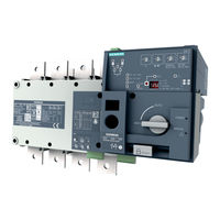
Siemens SENTRON Manual (224 pages)
Transfer Switching Equipment and Load Transfer Switches
Brand:
Siemens
| Category:
Switch
| Size: 22.82 MB
Table of Contents
Legal Information
4
Table of Contents
5
1 Introduction
9
2 General Information
11
Certification
11
3 Product Information
13
Product Description
13
Design of the 3KC4 and 3KC8 Transfer Switching Equipment
14
Current Ratings of the 3KC4 and 3KC8 Transfer Switching Equipment
18
Product Family
21
The Product Families 3KC4 and 3KC8 from 250 a to 3200 a
21
Use of 3KC4 and 3KC8 Transfer Switching Equipment
22
Properties of the 3KC4 and 3KC8 Transfer Switching Equipment
22
Application Areas of the 3KC4 and 3KC8 Transfer Switching Equipment
23
4 Functions
25
5 Mounting
27
Mounting Position
27
Installing the 3KC4 and 3KC8 Transfer Switching Equipment
27
Dimensions of the Cover Frame for Door Cut-Out
30
6 Connection
31
Network Types
31
Three-Phase 4-Wire Network with Neutral (3PH + N)
32
Circuit Diagram for the 3KC4 Transfer Switching Equipment - 4-Pole Transfer Switching Equipment
32
Circuit Diagram for the 3KC8 Transfer Switching Equipment - 4-Pole Transfer Switching Equipment
33
Three-Phase 3-Wire Network Without Neutral (3PH)
33
Equipment
34
Circuit Diagram for the 3KC8 Transfer Switching Equipment - 4-Pole Transfer Switching
35
Equipment
35
Circuit Diagram for the 3KC8 Transfer Switching Equipment - 3-Pole Transfer Switching Equipment
36
Single-Phase Network with Neutral (1PH + N)
37
Circuit Diagram for the 3KC4 Transfer Switching Equipment - 3-Pole Transfer Switching
37
Equipment
37
Circuit Diagram for the 3KC8 Transfer Switching Equipment - 3-Pole Transfer Switching
38
Equipment
38
Connecting the Main Circuit
39
Connecting Terminals of the Transfer Switching Equipment
39
Load Connection
40
Arrangement of the Power Supply Systems
40
Connection of Transfer Switching Equipment for Current Ratings 250 a to 1600 a
42
Connecting Bridging Bars on the Load Side
42
Connecting Current Ratings 250 a to 1600 a to the Main Circuit
46
Connection of Transfer Switching Equipment for Current Ratings 2000 a to 3200 a
49
Copper Bar Connection Kit
49
Connecting Current Ratings 2000 a to 3200 a to the Main Circuit (on the Line Side)
55
Connecting Current Ratings 2000 a to 3200 a to the Main Circuit (on the Load Side)
65
Connecting the Control Circuit
72
Inputs and Outputs of the Motor Operator
72
Overview of Motor Operator
72
Connecting the Inputs and Outputs of the Motor Operator
73
Power Supply of the Motor Operator (3KC4 Only)
75
Mounting and Connecting the Dual Power Supply (DPS)
77
Installing and Connecting an Autotransformer (400 V / 230 V)
79
Auxiliary Switch of the Transfer Switching Equipment
81
Installing Auxiliary Switches 250 a to 630 a
82
Installing Auxiliary Switches of Current Rating 800 a to 1600 a
84
Inputs and Outputs of the Electronic Module (3KC8 Only)
88
Connecting the Inputs and Outputs of the Electronic Module (3KC8 Only)
89
Installing Accessories for the Electronic Module
89
Connecting Power Supply Kit 3KC9830-, 3KC9831- (4-Pole)
92
Connecting the Auxiliary Conductor Terminal 3KC9822-, 3KC9832- for a Three-Phase 3-Wire Network (3-Pole)
95
Connecting Power Supply Kit 3KC9833-, 3KC9834- for Single-Phase Network
98
7 Operation
101
Operating Modes of the Transfer Switching Equipment
101
Remote Mode
102
Manual Operation
103
Padlocking Mode
104
Automatic Mode (3KC8 Only)
105
Functions of the Inputs and Outputs
106
Inputs and Outputs of the Motor Operator
106
Outputs of the Motor Operator
111
Auxiliary Switches
114
Inputs and Outputs of the Electronic Module (3KC8 Only)
115
Inputs for Voltage Measurement and Power Supply
115
Control Inputs of the Electronic Module
118
Functions of the Control Inputs for Network / Generator Application
119
Functions of the Control Inputs for Network / Network Application
121
Outputs of the Electronic Module
123
Remote Mode
126
Impulse Logic
126
Continuous Operation Logic
129
Automatic Mode - Programming of the Electronic Module (3KC8 Only)
132
Step 1: Preset Network Conditions
132
Step 2: Setting the Potentiometer
134
Step 3: Automatic Configuration of the Transfer Switching Equipment (Only with Potentiometer un = 0)
136
Step 4: Saving the Configuration
137
Step 5: Switching the 3KC8 Transfer Switching Equipment to Automatic Mode
137
8 Commissioning
139
Commissioning the 3KC4 Transfer Switching Equipment
139
Commissioning the 3KC8 Transfer Switching Equipment
141
9 Accessories
145
Terminal Covers
146
Mounting Terminal Covers
147
Phase Barriers
148
Mounting Phase Barriers
149
Terminal Plates
150
Mounting Terminal Plates
151
Mounting Spacers
153
Fitting Mounting Spacers
153
Bridging Bars
154
Copper Bar Connection Kit
155
Autotransformer
157
Dual Power Supply (DPS, 3KC4 Only)
158
Power Supply Kit 3KC9830-, 3KC9831- (4-Pole, 3KC8 Only)
159
Auxiliary Conductor Terminal 3KC9822-, 3KC9832- (3-Pole, 3KC8 Only)
160
Power Supply Kit 3KC9833-, 3KC9834- (2-Pole, 3KC8 Only)
161
Cover Frame (3KC8 Only)
162
Auxiliary Switches
163
Display (3KC8 Only)
164
Connection Cable (3KC8 Only)
167
Sealable Cover (3KC8 Only)
168
Motor Operator
170
Electronic Module (3KC8 Only)
175
10 Service and Maintenance
177
Fault Rectification
177
Fault States and Fault Detection on the 3KC4 Transfer Switching Equipment
177
Fault States and Fault Detection on the 3KC8 Transfer Switching Equipment
179
Regular Service and Maintenance
181
11 Technical Specifications
183
Technical Specifications 3KC4 and 3KC8 from 250 a to 1000 a
183
Technical Specifications 3KC4 and 3KC8 from 1250 a to 3200 a
186
Technical Specifications of the Electronic Module
189
12 Dimension Drawings
191
Dimension Drawings of the 3KC4 Transfer Switching Equipment
192
Dimension Drawings of the 3KC8 Transfer Switching Equipment
198
13 Applications
205
Transfer between Two Sources with One Outgoing Load
206
Transfer between Two Sources with Two Outgoing Loads
207
Transfer between Three Sources with One Outgoing Load
209
Transfer between Three Sources with Two Outgoing Loads
210
Transfer between Two Loads with One Incoming Source (with 3KC4 Transfer Switching Equipment Only)
213
Appendix
215
Environmental Conditions
215
A.1 Environmental Conditions
215
Operating Conditions
216
Temperature
216
Humidity
216
Altitude Conditions
216
A.2 Operating Conditions
216
Storage Conditions
217
Temperature
217
Storage Position
217
A Appendix
217
ESD Guidelines
221
Electrostatic Sensitive Devices (ESD)
221
List of Abbreviations
223
Advertisement
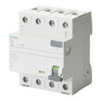
Siemens SENTRON Manual (90 pages)
Brand:
Siemens
| Category:
Circuit breakers
| Size: 3.05 MB
Table of Contents
Table of Contents
4
Product Portfolio
6
Introduction
8
Protection through Residual Current Protective Devices
9
Additional Protection with I
9
(Previously "Protection against Direct Contact")
9
Fault Protection (Previously "Protection against Indirect Contact")
13
Fire Protection
14
Residual Current Protective Devices
15
Types of Rccbs
15
Type AC
17
Type a
17
Type F
17
Type B
17
Type B
18
Classification of Residual Current Protective Devices
18
Basic Design and Method of Operation
21
Type a RCCB
21
SIQUENCE Universal Current-Sensitive RCCB Type B and Type B
24
Features and Application Areas
25
Rccb
25
RCBO Type AC, Type a and Type F
26
SIQUENCE Universal Current-Sensitive RCCB Type B and Type B
29
SIQUENCE Universal Current-Sensitive RCBO Type B and Type B
34
RC Units for Installation on Miniature Circuit Breakers
35
SIGRES Rccbs (for Harsh Ambient Conditions)
36
Type K Super-Resistant
37
Type S Selective
39
Versions for 50 to 400 Hz
40
4.4.10 Versions for 500 V Operational Voltage
40
4.4.11 RCCB with Left-Side N Connection
40
Additional Components for Rccbs
41
Remotely Controlled Mechanism (RC)
41
Auxiliary Switches
43
Additional Components
43
Notes on Installation and Use
44
General Notes
44
Selection of Protective Devices
44
Use of Residual Current Protective Devices
46
Choosing the Right Residual Current Protective Device
48
Type A, Type F or Type B / Type B
49
What Protection Goal Must be Achieved
49
What Electrical Interference Occurs and How Is It Handled
50
Applications
53
Configuration
61
Back-Up Protection
64
Protection against Thermal Overload
66
Troubleshooting
67
4-Pole Rccbs in a 3-Pole Network
68
Mrcds and Rcms
69
Modular Residual Current Devices (Mrcds)
69
Residual Current Monitoring Devices (Rcms)
70
Outlook
73
Sources
74
Appendix
75
Key Terms and Definitions (According to DIN VDE 0100-200)
75
Power Systems and Protective Devices
78
TN System
79
TT System
80
System
82
Summary
83
Key Terms and Definitions for Specifying the Switching Capacity
84
Installation Regulations for Electrical Installations with Residual Current Protective Devices
85
10. List of Figures and Tables
87
Siemens SENTRON Instructions Manual (76 pages)
Residual Current Protective Devices
Brand:
Siemens
| Category:
Protection Device
| Size: 2.98 MB
Table of Contents
Table of Contents
4
1 Overview
6
2 Introduction
8
3 Protection through Residual Current Protective Devices
8
Additional Protection (Previously „Protection against Direct Contact") with I
9
Δn
9
Fault Protection (Protection against Indirect Contact)
12
Fire Protection
13
4 Residual Current Protective Devices
14
Types of Residual Current Protective Devices
14
Type AC
16
Type a
16
Type F
16
Type B
16
Type B
17
Classification of Residual Current Protective Devices
17
Basic Design and Method of Operation
19
Type a RCCB
19
SIQUENCE Universal Current-Sensitive RCCB Type B and Type B
21
Features and Application Areas
22
Rccb
22
RCBO (Type Ac/Type A, Type F)
23
SIQUENCE Universal Current-Sensitive RCCB Type B and Type B
26
SIQUENCE Universal Current-Sensitive RCBO Type B und Type B
30
RC Units for Installation on Miniature Circuit Breakers
31
SIGRES RCCB (for Harsh Ambient Conditions)
31
Type K Super-Resistant
32
Type S Selective
34
Versions for 50 to 400 Hz
35
Versions for 500 V Operational Voltage
35
Residual Current Operated Circuit Breaker with N-Connection on the Left Side
35
Additional Components for Residual Current Operated Circuit Breakers
36
Remote Controlled Operating Mechanism (RC)
36
Auxiliary Switch
37
Additional Components
37
5 Notes on Installation and Use
38
General Notes
38
Selection of Protective Devices
38
Use of Residual Current Protective Devices
40
Choosing the Right Residual Current Protective Device
42
Type A, Type F or Type B/ Typ B
43
What Protection Goal Must be Achieved
43
What Electrical Interference Occurs and How Is It Handled
44
Leakage Currents
44
High Load Currents
45
Overvoltages and Surge Current Load
46
Special Features Regarding the Use of SIQUENCE Universal Current-Sensitive Residual Current Protective Devices (Type B and Type B+)
47
Applications
47
Residual Currents at Different Fault Locations, with a Frequency Converter (FC) as an Example
47
Configuration
52
Causes of Excessive Leakage Currents and Possibilities of Reducing Them
53
Back-Up Protection
55
Protection against Thermal Overload
57
Troubleshooting
58
4-Pole Residual Current Operated Circuit Breakers in a 3-Pole Network
59
6 Residual Current Monitoring Devices (RCM)
59
7 Outlook
61
8 Source Specified
62
9 Appendix
63
10 List of Figures and Tables
74
Advertisement
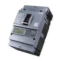
Siemens SENTRON Configuration Manual (80 pages)
Protective devices Selectivity for 3VA molded case circuit breakers
Brand:
Siemens
| Category:
Power distribution unit
| Size: 10.43 MB
Table of Contents
Table of Contents
5
1 Introduction
7
2 Selectivity - Terms and Definitions
9
3 Methods of Implementing Selectivity Using Circuit Breakers
13
Starting Point
15
Selectivity in the Overload Zone
15
Example
16
Circuit Breaker Parameters
17
Tripping Characteristics of Circuit Breakers
18
Current Selectivity
19
Circuit Breaker Parameters
20
Tripping Characteristics of Circuit Breakers
21
Different Short-Circuit Currents at Different Fault Locations
22
Time Selectivity
23
Circuit Breaker Parameters
26
Tripping Characteristics of Circuit Breakers
27
Implementation of Total Selectivity
28
Zone Selective Interlocking
30
Zone Selective Interlocking and Time Selectivity
33
Setting of Circuit Breakers
36
Dynamic Selectivity
40
Implementation of Dynamic Selectivity
41
Let-Through Energy Diagram
43
Example
44
4 Selectivity Implemented by Combinations of Protective Devices
47
Molded Case Circuit Breakers and Downstream Fuse
47
Fuse and Downstream Molded Case Circuit Breaker
50
Fuse and Downstream Miniature Circuit Breaker
53
Fuse and Downstream Fuse
53
5 Selectivity with Parallel Incoming Feeders
57
Selectivity with Two Identical Incoming Feeders
58
Symmetrical Distribution (Ideal Scenario)
59
Asymmetrical Distribution
59
Selectivity with Three Identical Incoming Feeders
60
Fault Within the Protection Zone of the Downstream Protective Device
60
Fault between Transformer Terminals and Incoming Feeder Circuit Breaker
61
Selectivity with Bus-Couplers
63
Sources of Information and Other Documentation
68
6 Selectivity and Undervoltage Protection
69
3 VA Selectivity Tables
71
List of Abbreviations
73
A.1 List of Abbreviations
73
Glossary
75
Siemens SENTRON Product Manual (46 pages)
PAC expansion module
Brand:
Siemens
| Category:
Control Unit
| Size: 2.93 MB
Table of Contents
Table of Contents
5
1 Introduction
7
Scope of Delivery
7
Latest Information
7
Security Information
8
Open Source Software
9
2 Description
11
Area of Application
11
Performance Features of the I(N), I(Diff), Analog Module
11
Design
13
3 Installation
15
Installation Location
15
Installation Steps
16
4 Connection
17
Safety Information
17
Connections
18
5 Commissioning
27
Overview
27
Setting the Expansion Module Parameters
28
Parameterizing with Powerconfig
31
Reading out Measured Values
32
6 Service and Maintenance
33
Calibration
33
Firmware Update
33
Troubleshooting Guide
33
Warranty
34
7 Technical Specifications
35
Appendix
39
Modbus Measured Quantities with Function Codes 0X03 and 0X04
39
Average Value Quantities
39
Index
43
Siemens SENTRON Installation Manual (20 pages)
3/6 Bus Plug with Optional SEM3 Package
Brand:
Siemens
| Category:
Power distribution unit
| Size: 3.67 MB
Table of Contents
Table of Contents
3
1 Definitions
4
Qualified Personnel
4
Danger
4
Warning
4
Caution
4
Tip
4
2 References
4
3 Storage Instructions
4
4 Preparing for Installation
4
5 Basics of SEM3
4
Energy Management System
5
SEM3 Features
5
6 Installation & Removal
5
Installation Conditions
5
SEM3™ FCC Notice
6
Control Wiring
6
Other SEM3™ Components
8
7 Configuring the Metering System
10
Assign Static IP Address
11
Web User Interface
12
Addressing the Meter Racks
12
8 Sample Network Topology
14
9 Additions to the Network
15
10 Contact Information and Support
15
11 Notes
16
Siemens SENTRON Configuration Manual (14 pages)
Protective devices Selectivity for 3VA molded case circuit breakers
Brand:
Siemens
| Category:
Power distribution unit
| Size: 7.88 MB
Advertisement
Related Products
Siemens SENTRON VL Series
Siemens SEH62.1
Siemens SE
Siemens SEL
Siemens SER
Siemens SCALANCE XR-300M
Siemens SIMATIC NET SCALANCE X005TS
Siemens SIMATIC NET RUGGEDCOM RS930L
Siemens SIMATIC NET RUGGEDCOM RS900G
Siemens SIMATIC NET SCALANCE X-100
Siemens Categories
Industrial Equipment
Controller
Control Unit
Oven
Washer
More Siemens Manuals
Login
Sign In
OR
Sign in with Facebook
Sign in with Google
Upload manual
Upload from disk
Upload from URL