Sign In
Upload
Manuals
Brands
Siemens Manuals
Circuit breakers
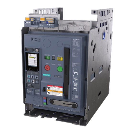
SENTRON 3WA1
Siemens SENTRON 3WA1 Manuals
Manuals and User Guides for Siemens SENTRON 3WA1. We have
1
Siemens SENTRON 3WA1 manual available for free PDF download: Manual
Siemens SENTRON 3WA1 Manual (576 pages)
Brand:
Siemens
| Category:
Circuit breakers
| Size: 55.7 MB
Table of Contents
Table of Contents
5
Introduction
19
Scope of Validity of this Document
19
Target Readers of this Documentation
19
Technical Support
19
Reference Documents
20
Advanced Training Courses
20
Safety Instructions
21
Security Information
22
Open Source Software
22
More Information on Open Source Software for 3WA Circuit Breakers
23
Standards
24
Abbreviations
24
Description
25
Overview - Applications and Portfolio
25
Properties
25
Portfolio of the 3WA1 Circuit Breaker
27
Advantages
28
Circuit Breakers and Non-Automatic Circuit Breakers
29
Distinction between Circuit Breakers and Non-Automatic Circuit Breakers
29
Design
30
Circuit Breakers
30
Guide Frame
31
Secondary Disconnect Terminals
36
Circuit Breaker Identification
38
Rating und Accessory Labels of Circuit Breaker
38
Guide Frame Rating Label
40
Operation
41
Charging the Stored-Energy Spring
41
Closing and Opening
42
Racking the Circuit Breaker in the Guide Frame
44
Commissioning Checklist
45
Protection System
47
General Description of Function
47
Option Plug
48
Guideline for Setting the Protection Parameters
50
Time-Current Characteristic
50
Description of the Protective Functions
52
General Description
52
Long Time LT
52
Short Time ST
56
Instantaneous Short-Circuit Protection INST
57
Neutral Protection N
58
Ground-Fault Alarm
59
Ground-Fault Protection GF
60
Ground-Fault Protection GF Hi-Z
63
Directional Short Time Dst
66
Reverse Power Protection RP
68
Enhanced Protective Functions EPF
69
Tolerances for Protection Functions
70
DAS+ Maintenance Mode
74
Activation Limits and Power Supply
78
ETU300 Electronic Trip Unit
79
Overview of Variants
79
Operator Controls and Displays
80
Overview
80
Operating Keys
81
LED Displays
81
Rotary Coding Switches
83
Interfaces
83
Interface for External Voltage Supply Via the TD400
83
Digital Input and Output
84
External Current Sensor
85
Rear Interfaces
86
Protection Parameters
86
Introduction
86
Setting Range
87
Parameter DAS+ Maintenance Mode
88
DAS+ Maintenance Mode
88
Electronic Trip Unit ETU600
89
Overview of Variants
89
Operator Controls, Displays and Voltage Tap Module
90
Overview
90
Display and Operating Keys F1 to F4
91
LED Displays
91
Rotary Switch
93
Voltage Tap Module
93
Display and Menu Structure
95
Operating Philosophy
95
Menu Structure
97
Start Screen
98
Display after a Trip
101
Display in Case of a Warning
103
Display of an Error Message
104
Interfaces
105
Bluetooth and USB-C Interface
105
Digital Input and Output
109
Digital Output for Ground-Fault Alarm REF
111
External Current Sensors
112
Battery
113
Rear Interfaces
114
Protection Parameters
115
Introduction
115
Parameter Set a
115
Parameter Set B (Optional)
116
Setting Range for Parameter Sets a and B
116
Enhanced Protective Functions EPF
120
Parameter DAS+ Maintenance Mode
122
Zone-Selective Interlocking ZSI Parameters
122
DAS+ Maintenance Mode
123
Technical Specifications
125
ETU600 Commissioning
125
Grid Parameters
126
Wiring Configuration
127
Metering
127
Local Interfaces
128
Display
128
Digital Input
128
Digital Output
128
Module Monitoring
129
Remote Access Protection
129
System Time
129
Function Packages
130
General
130
Ground-Fault Alarm
130
Directional Protective Functions
130
Enhanced Protective Functions
131
Second Set of Protection Parameters
131
Metering Values
131
Metering Function (Power Metering Function)
132
Communication and System Connection
140
Cubiclebus²
140
The Bus System
140
Technical Specifications
142
Selecting the Power Supply
142
Firmware Update
143
COM190 and COM150 Communication Modules
146
Overview
146
COM190 Communication Module
147
COM150 Communication Module
152
Common Functions and Connections
156
Commissioning
161
Access Protection Functions
165
Resetting to Factory Settings
169
System Time
171
Status Acquisition with Breaker Status Sensor BSS200
173
Self-Monitoring and Diagnostics
175
Internal Self-Test
175
General
175
Internal Self-Test ETU300
175
Internal Self-Test ETU600
176
Software-Assisted Testing
178
Circuit Breaker Operating Principle
178
Test Functions
179
SENTRON Powerconfig Configuration Software
183
Display of Errors and Alarms
183
Trip Log
187
Zone-Selective Interlocking ZSI
189
Advantage
189
Structure and Principle of Operation of the ZSI System
189
Monitoring and ZSI Test Function
191
Parameterization
191
Compatibility
192
Application Examples
193
Example: Radial System with Three Grading Levels
193
Example of Multiple Infeed with Coupler Circuit Breaker
196
Example of Branch Circuit with Fuse
197
Example of Integrating the Medium-Voltage Protection Relay
200
Applications
201
Use in Systems with Isolated Transformer Neutral Point (IT Systems)
201
General
201
Selection Criteria
202
Fault Situation
203
Using the 3WA Circuit Breaker for Motor Protection
204
Transfer Control
208
General
208
Transfer Control with Two 3WA Circuit Breakers
209
Transfer Control with Three 3WA Circuit Breakers
209
Further Information
209
Applications with Closing Coil and Shunt Trip
210
Overview
210
Connecting the Closing Coil
212
Connection of the First Shunt Trip
213
Connection of the Second Shunt Trip
214
Electrical Interlocks for Switching Via Communication
214
Electrical Closing Interlock
217
DSP800 Display
218
Powermanager
221
Energy Management in Accordance with ISO 50001
221
Features
222
Functions
223
TÜV Certificate of Conformity for Energy Management
223
7KN Powercenter 3000
224
Iot Gateway for the Intelligent Power Distribution Equipment
224
Iot Data Platform
225
Parameterization and Settings
226
SENTRON Powermind
227
Accessories
229
Overview
229
Preparatory and Concluding Installation Steps for the Installation of Internal Accessories
231
Control and Signaling Accessories
236
Closing Coil, Shunt Trip, Undervoltage Release
236
Description
236
Technical Specifications
239
Part Number
243
Capacitor Trip Device for Shunt Trips
245
Description
245
Technical Specifications
245
Article Number
245
Remote Trip Alarm Reset Coil (Incl. Automatic Reset of the Reclosing Lockout)
246
Description
246
Technical Specifications of the Remote Trip Alarm Reset Coil
247
Article Number
247
Emergency OPEN Button
248
Description
248
Article Number
248
Digital Input/Output Modules
248
Technical Specifications
254
Article Number
258
Spring Charging Motor
259
Description
259
Technical Specifications
260
Article Number
260
Motor Disconnect Switch
261
Description
261
Article Number
261
Mechanical Operating Cycles Counter
262
Description
262
Article Number
262
External Trip Controller ETC600
263
Description
263
Technical Specifications and Connection
264
Article Number
266
Second Tripping Solenoid with Reclosing Lockout
267
Description
267
Article Number
267
Accessory Auxiliary Switches and Signaling Switches
268
Overview
268
Auxiliary Switches S1 to S8
268
Description
268
Technical Specifications
269
Article Number
270
Ready-To-Close Signaling Switch
270
Description
270
Technical Specifications
271
Article Number
271
Spring Charge Signaling Switch
272
Description
272
Technical Specifications
273
Article Number
273
Trip Alarm Switch
274
Description
274
Technical Specifications
275
Part Number
275
Position Signaling Switch Module for Guide Frame
276
Description
276
Technical Specifications
280
Article Number
281
Accessories for Main Connections
282
Main Connections for Fixed-Mounted Circuit Breakers
282
Description
282
Technical Specifications
287
Article Number
288
Main Connections for Withdrawable Circuit Breakers
290
Description
290
Technical Specifications
297
Part Number
297
Accessories for Secondary Disconnect Terminals
300
Secondary Disconnect Terminals for Fixed-Mounted Circuit Breakers
300
Description
300
Connection
300
Part Number
301
Secondary Disconnect Terminals for Withdrawable Circuit Breakers
301
Description
301
Connection
302
Part Number
302
Conversion Kit for Withdrawable Circuit Breakers and Rating Coding of the Guide Frame
303
Conversion Kit for Converting Fixed-Mounted Circuit Breakers/Non-Automatic Circuit Breakers into Withdrawable Circuit Breakers
303
Description
303
Technical Specifications
304
Part Number
304
Equipment-Dependent Coding
305
Description
305
Article Number
305
Accessories for Protection against Unauthorized Operation
306
Overview of Locking Devices and Locking Provisions
306
Locking Provision to Prevent Unauthorized Closing - Safe Open
309
Description
309
Activation
310
Part Number
311
Local Electric Close
312
Description
312
Connection
313
Activation
313
Part Number
313
Locking Provision for Charging Handle for Padlocks
314
Description
314
Activation
314
Article Number
314
Cover for the Electronic Trip Unit
315
Description
315
Article Number
315
Locking Provision to Prevent Unauthorized Closing of the Withdrawable Circuit Breaker
316
Description
316
Activation
317
Part Number
317
Locking Provision with Padlock for the Racking Handle of the Racking Mechanism
318
Description
318
Activation
318
Locking Provision with Safety Lock for the Racking Handle
319
Description
319
Activation
319
Part Number
320
Shutters
321
Article Number
321
Locking Provision to Prevent Opening of the Control Cabinet Door When the Circuit Breaker Is Closed
322
Description
322
Activation / Override
323
Article Number
323
Locking Provision to Prevent Racking of the Withdrawable Circuit Breaker in the Disconnected Position
324
Description
324
Activation
325
Part Number
325
Locking Provision to Prevent Racking of the Withdrawable Circuit Breaker When the Control Cabinet Door Is Open
326
Description
326
Activation
326
Article Number
327
Locking Provision to Prevent Closing of the Withdrawable Circuit Breaker When the Control Cabinet Door Is Open
327
Description
327
Activation / Override
328
Part Number
328
Interlocking
329
Mechanical Interlocking (Bowden Cable Interlocking)
329
Description
329
Part Number
333
Interlocking of Two Circuit Breakers Using a Bowden Cable
334
Interlocking of Three Circuit Breakers (One of Three) Using a Bowden Cable
335
Interlocking of Three Circuit Breakers Using a Bowden Cable
336
Interlocking of Three Circuit Breakers, Two of Which Are Interlocked, Using a Bowden Cable
337
Interlocking of Three Circuit Breakers Using a Bowden Cable
338
Interlock for Mechanical Close/Open
339
Description
339
Activation
340
Article Number
340
Interlock System to Prevent Unauthorized Closing
341
Description
341
Activation
341
Article Number
341
Accessories for Integration in the Power Distribution Equipment
342
Door Sealing Frame
342
Description
342
Article Number
342
IP55 Protective Cover
343
Description
343
Article Number
344
Arc Chute Cover
345
Description
345
Article Number
345
Grounding Connection between the Guide Frame and the Circuit Breaker
346
Description
346
Article Number
347
Support Brackets
348
Description
348
Article Number
348
Accessories for the ETU300 and ETU600 Electronic Trip Units
349
Option Plug
349
Description
349
Article Number
350
External Current Sensor for Neutral Pole
351
Description
351
Technical Specifications
351
Article Number
352
Voltage Tap Module VTM for ETU600
353
Description
353
Article Number
354
Adapter for the Activation of the ETU300
355
Description
355
Connection
355
Article Number
356
Internal Current Sensors Without Energy Cores
357
Description
357
Technical Specifications
358
Connection
358
Article Numbers
359
Ready4Com Thanks to BSS200 Breaker Status Sensor for ETU600
360
Description
360
Technical Specifications
361
Article Number
361
ZSI200 Zone Selective Interlocking Module
362
Description
362
Technical Specifications
363
Article Number
364
Replacement Battery for ETU600
365
Description
365
Replacing the Battery
365
Article Number
365
Internal Voltage Tap on Main Current Paths
366
Voltage Tap Conversion
366
Description
366
Article Number
366
Retrofit of the Internal Voltage Tap
368
Description
368
Article Number
369
Connection of an External Voltage Transformer
370
Description
370
Connection
371
Article Number
372
Function Packages for the ETU600 Electronic Trip Unit
373
Description
373
Function Packages for Protection and Alarm Functions
373
Article Number
374
Function Packages for Enhanced Protective Functions EPF
374
Description
374
Article Number
375
Function Packages for Function Extensions
375
Description
375
Function Packages for Metering Values
376
Description
376
Article Number
377
Communication Interface
378
PROFINET Io/Modbus TCP Module COM190
378
Description
378
Technical Specifications
379
Article Number
380
Modbus RTU Module COM150
381
Description
381
Technical Specifications
382
Article Number
383
Position Signaling Switch Module for Connection to the Communication Module
384
Description
384
Article Number
384
Cubiclebus² Terminating Resistor
385
Description
385
Technical Specifications
385
Article Number
385
Mounting Adapter for Cubiclebus² Modules
386
Description
386
Article Number
386
Special Packaging
387
Description
387
Article Number
387
Inspection and Maintenance
389
General
389
Safety Regulations
391
Planning of Inspection and Maintenance
392
Inspection Interval
392
Scope
393
Logging
395
Performing Inspection
396
General
396
Visual Inspection
396
Check of the Available Documentation and of the Rating/Accessory Label
397
Testing of Mechanical Function of the Circuit Breaker
397
Testing of Mechanical Function of the Withdrawable Circuit Breaker and the Guide Frame
398
Testing of Auxiliary Circuits and of Cables to External Current Sensors
398
Testing of Mechanical and Electrical Function of Internal Accessories
399
Testing of Settings and Inspection of Electronic Trip Unit
400
Inspection of the Arc Chutes, Arc Chute Cover and the Contact System
400
Testing of the Function of the Cubiclebus² Modules
401
Preparing for Maintenance Work
402
Maintaining the Arc Chutes
405
Maintaining the Main Contacts
407
Introduction
407
Maintaining the Main Contacts and Replacing the Contact System
408
Article Number
416
Decommissioning
418
Technical Specifications
419
Circuit Diagrams
419
Secondary Disconnect Terminal Blocks X5 to X9 and Their Terminal Markings
419
Terminal Connection Diagrams of Secondary Disconnect Terminal
420
ETU300 Terminal Assignment Diagram
420
ETU600 Terminal Assignment Diagram
421
Terminal Assignment Plan Supplement for Circuit Breakers with the K60 Option (with Integrated Undervoltage Release)
423
Closing Coil CC / CC-COM
424
Remote Trip Alarm Reset Coil RR
424
Shunt Trip ST / ST-COM / ST2
424
Capacitor Trip Device for Shunt Trips
425
Undervoltage Release UVR / UVR-T
425
Second Tripping Solenoid F6 with Reclosing Lockout
426
External Trip Controller ETC600
426
Digital Input / Output Module IOM230
427
Digital Input/Output Module IOM350
427
Spring Charging Motor
428
Motor Disconnect Switch
428
Auxiliary Switch
428
Ready-To-Close Signaling Switch S20
429
Spring Charge Signaling Switch S21
429
Trip Alarm Switches S24 and S25
429
PSS and PSS COM Position Signaling Switch Modules
430
Local Electric Close S10
431
ZSI200 Zone Selective Interlocking Module
432
COM150 Communication Module
432
COM190 Communication Module
433
Breaker Status Sensor BSS200
433
Dimension Drawings
434
3WA1 - Size 1
434
Fixed-Mounted Circuit Breakers
434
Withdrawable Circuit Breakers
440
3WA1 - Size 2
448
Fixed-Mounted Circuit Breakers
448
Withdrawable Circuit Breakers
455
3WA1 - Size 3
465
Fixed-Mounted Circuit Breakers
465
Withdrawable Circuit Breakers
470
Safety Clearances
477
3WA - Size 1
477
3WA - Size 2
479
3WA - Size 3
481
Accessories and Door Cutouts
483
Capacitor Storage Device
483
COM190 Communication Module
483
External Current Sensor for the Neutral Pole (N-CT)
484
Support Brackets
486
Door Cutout/Protective Cover IP55
487
Door Sealing Frame
488
Interlocks and Locking Provisions
489
Technical Specifications of 3WA Circuit Breakers
491
Basic Data for Sizes 1 to 3
491
Size 1
492
Basic Data
492
Breaking Capacity
493
Ampacity, Power Loss
494
Switching Times, Endurance (Operating Cycles)
494
Minimum Cross-Sections of Main Conductors
496
Size 2
497
Basic Data
497
Breaking Capacity for AC
498
Ampacity, Power Loss for AC
499
Switching Times, Endurance (Operating Cycles) for AC
499
Minimum Cross-Sections of Main Conductors for AC
500
Breaking Capacity for DC
501
Ampacity, Power Loss for DC
502
Switching Times, Endurance (Operating Cycles) for DC
502
Minimum Cross-Sections of Main Conductors for DC
504
Size 3
504
Basic Data
504
Breaking Capacity
505
Ampacity, Power Loss
506
Switching Times, Endurance (Operating Cycles)
506
Minimum Cross-Sections of Main Conductors
508
Connection Options for Auxiliary Conductor Plug-In System
508
Ambient Conditions
509
Installation Altitudes
510
Standards
510
Approvals
511
Failure Probability Acc. to B10 and B10D
512
Electromagnetic Compatibility
516
Integration in Power Distribution Equipment
517
Compact Design
517
Influencing Factors
518
Derating in the Power Distribution Equipment
519
Overview
519
Derating 3WA11
519
Derating 3WA12
524
Derating 3WA13
526
Requirement According to IEC 61439
528
Standard IEC 61439
528
Simplified Integration
529
Structural Integration in Power Distribution Equipment
529
Using 3WA Circuit Breakers in 3WL Guide Frames
530
Retrofit: Simple Replaceability in Existing Power Distribution Equipment
531
Checklist for Replacing 3WL with 3WA Circuit Breaker According to IEC 61439-2
537
Phase Barriers and Horizontal Partitions
539
Insulation Test of the Power Distribution Equipment
541
Main Connection
542
Troubleshooting
543
Troubleshooting for Circuit Breaker
543
Troubleshooting for the ETU600 Electronic Trip Unit
545
8.3 Troubleshooting for COM150 / COM 190 Communications Module
549
Disposal
551
End of Maximum Service Life
551
Disposal of Low-Voltage Circuit Breakers
551
Disposal of Waste Electronic Equipment
551
Appendix
553
Basic Settings of the Electronic Trip Unit on Delivery
553
Time-Current Characteristic of the ETU300 Electronic Trip Unit
559
Time-Current Characteristic of the ETU600 Electronic Trip Unit
560
ETU600 Menu Structure
561
Device Numbers According to IEEE Standard C37.2
564
ZSI System over Seven Grading Levels
566
Overview of Possible Coding Variants
567
ESD Guidelines
569
Electrostatic Sensitive Devices (ESD)
569
List of Abbreviations
571
Advertisement
Advertisement
Related Products
Siemens SENTRON 3WA Air
Siemens 3WX35 83-8 Series
Siemens 3WX31 83-8KB
Siemens 3WX31 83-8PB
Siemens 3WX3668-2J.00
Siemens 3WX3667-1JA00
Siemens 3WL10 0 Series
Siemens 3WX3666-4JA00
Siemens 3WX3631-1JF20
Siemens 3WX3651-1J series
Siemens Categories
Industrial Equipment
Controller
Control Unit
Oven
Washer
More Siemens Manuals
Login
Sign In
OR
Sign in with Facebook
Sign in with Google
Upload manual
Upload from disk
Upload from URL