Sign In
Upload
Manuals
Brands
Siemens Manuals
Controller
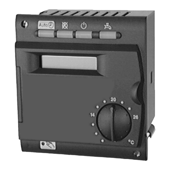
RVA47.320
Siemens RVA47.320 Manuals
Manuals and User Guides for Siemens RVA47.320. We have
1
Siemens RVA47.320 manual available for free PDF download: User Manual
Siemens RVA47.320 User Manual (166 pages)
Cascade Controller for modulating gas-fired Boilers
Brand:
Siemens
| Category:
Controller
| Size: 2.66 MB
Table of Contents
Table of Contents
3
1 Summary
8
Brief Description
8
Features
9
Range of Products
11
Field of Use
12
Product Liability
12
2 Handling
13
Installation
13
Mounting Location
13
Regulations for Installation
13
Mounting Procedure
13
Required Cut-Out
15
Orientation
15
Electrical Installation
16
Regulations for Installation
16
Wiring
16
Commissioning
18
Functional Checks
18
Parameter Settings for the Enduser
20
Overview of Enduser Parameters
21
Parameter Settings for the Heating Engineer
22
Overview of Heating Engineer Parameters
23
Parameter Settings for the OEM
27
Overview of OEM Parameters
28
Operation
30
Operating Elements
30
Operational Faults
31
3 Description of the Enduser Settings
32
User Interface
32
Heating Circuit Operating Modes
32
Operating Mode of D.h.w. Heating
33
Nominal Room Temperature Setpoint
34
Manual Operation
35
Setting the Clock
37
Time of Day
37
Weekday
37
Date (Day, Month)
38
Year
38
Time Switch Program for Space Heating
39
Preselecting the Weekday
39
Switching Times
40
D.h.w. Values
42
Nominal D.h.w. Temperature Setpoint
42
Heating Circuit Values
43
Reduced Room Temperature Setpoint
43
Frost Protection Setpoint of the Room Temperature
44
Summer / Winter Changeover Temperature of the Heating Circuit
44
Heating Curve Slope
46
Actual Values
48
Actual Value of the Room Temperature
48
Actual Value of Outside Temperature
48
Maintenance
49
Standard Time Switch Program for Heating Circuit and D.h.w
49
Time Switch Program for D.h.w. Heating
50
Preselecting the Weekday
50
Switching Times
50
Service
52
Displaying the BMU Error Code
52
Indication of Faults
53
4 Description of the Heating Engineer Settings
55
Service Values
55
Output Test
55
Input Test
55
Display of Plant Type
56
Displaying the PPS Communication
58
Actual Values
60
Actual Boiler Temperature Values of Bmus (Tkx)
60
Actual Value of Cascade Flow Temperature
60
Actual Value of the Cascade Return Temperature
61
Actual Value of Buffer Storage Tank Temperature
63
Actual Value of the D.h.w. Temperature (Tbwx)
63
Attenuated Outside Temperature
64
Composite Outside Temperature
65
Setpoints
66
Outside Temperature Source
66
Boiler Temperature Setpoint of Bmus
66
Setpoint of the Cascade Flow Temperature
67
D.h.w Temperature Setpoint
67
Nominal Room Temperature Setpoint
68
Room Temperature Setpoint
69
Flow Temperature Setpoint
69
Heat Generation Values
70
Existing Boilers
70
Display Lead Boiler
70
Remaining Number of Operating Hours for Changeover of Boiler Sequence
71
Burner Operating Hours BMU 1 - 4
72
Minimum Limitation of the Boiler Temperature Tkmin
72
Nominal Output of BMU 1 - 4
73
Configuration of Plant
74
Pump Function Output Q1
74
Use Sensor Input B70/B4
74
Heating Circuit Values
76
Parallel Displacement of the Heating Curve
76
Room Influence
76
Switching Differential of the Room Temperature
77
Minimum Limitation of the Flow Temperature Setpoint
78
Maximum Limitation of the Flow Temperature Setpoint
79
Type of Building Construction
80
Adaption of the Heating Curve
81
Maximum Forward Shift of Optimum Start Control
82
Optimum Start Control
83
Without Room Influence
83
With Room Influence
83
Maximum Forward Shift of Optimum Stop Control
84
Optimum Stop Control
84
D.h.w. Values
85
Reduced Setpoint of the D.h.w. Temperature
85
Release of D.h.w. Heating
85
24-Hour Operation - Setting 0
86
Operation According to Heating Program(S) with Forward Shift - Setting 1
86
Operation According to the D.h.w. Time Switch Program - Setting 2
87
Switching Program Circulating Pump
87
Assignment of D.h.w. Heating
88
Number of D.h.w. Charging Cycles
88
Once Per Day with a Forward Shift of 2.5 Hours Setting 0
89
Several Times Per Day with a Forward Shift of 1 Hour Setting 1
89
Type of D.h.w. Demand
89
Boost of the Flow Temperature Setpoint for D.h.w
90
D.h.w. Priority
91
Shifting Priority
92
Demand for Heat with Reduced D.h.w. Setpoint
94
Cascade Settings
95
Changeover of Boiler Sequence in a Cascade
95
Exemption from Automatic Changeover of the Boiler Sequence
96
Lead Boiler with a Fixed Changeover of the Boiler Sequence
97
Switch-On Delay Lag Boilers
98
Restart Lock of Bmus
98
LPB / System
99
LPB Device Address
99
LPB Segment Address
100
LPB Power Supply
100
Displaying the LPB Power Supply
101
Displaying the LPB Communication
101
Range of Action of Central Changeover
102
Automatic Summer / Winter Changeover
102
Central Standby Switch
103
Clock Mode
103
Winter- / Summertime Changeover
104
Summer- / Wintertime Changeover
105
Input H1
106
Changeover of Operating Mode (Remote Telephone Switch) - Setting 0 / 1
107
Minimum Setpoint of Flow Temperature Contact H1
108
Heat Generation Lock - Setting 3
108
Demand for Heat - Setting 4
109
Minimum Setpoint of Flow Temperature Contact H1
110
Maximum Value of Heat Demand Signal DC 0
111
Operating Action of the Contact Connected to H1
111
5 Description of the OEM Settings
112
Heat Generation Values
112
Minimum Limitation of the Boiler Temperature Setpoint OEM (Tkmin )
112
Oem
112
Maximum Limitation of the Boiler Temperature Setpoint
112
Pump Overrun Time
113
Minimum Limitation of the Boiler Return Temperature
113
Calibration of Actual Output Range of BMU 1-4
114
Heating Circuit Values
115
Gain Factor of Room Influence (KORR)
115
Constant for Quick Setback (KON)
116
Boost of Room Temperature Setpoint
117
Frost Protection for the Plant
118
Overtemperature Protection for the Pump Heating Circuit
119
Heat Gains
120
Adaption Sensitivity 1
120
Adaption Sensitivity 2
121
D.h.w. Values
123
Maximum Nominal Setpoint of D.h.w. Temperature
123
Switching Differential of the D.h.w. Temperature
123
Legionella Function
124
Setpoint of the Legionella Function
125
Protection against Discharging of D.h.w
125
Cascade Settings
127
Cascade Management Strategy
127
Type of Lead Boiler Operation
128
Running Time Strategies
129
Lower Limit of Output Range (Pmin)
131
Upper Limit of Output Range (Pmax)
132
Mandatory Time on Basic Stage
132
Minimum Temperature Differential at the Pressureless Header
133
Configuration of Plant
134
Continuous Display
134
General Values
135
Software Version
135
Device Operating Hours
135
6 Functions with no Settings
136
Chimney Sweep
136
Generating the Boiler Temperature Setpoint
136
Automatic 24-Hour Heating Limit
137
Without Room Influence
137
With Room Influence
138
Quick Setback with Room Sensor
139
D.h.w. Push
140
Pump Kick
141
Protection against Discharging after D.h.w. Heating
141
Overview of Pump Operation
142
Frost Protection
143
For the Boiler
143
For the D.h.w
143
7 Application Examples
144
Plant Types RVA47.320 - No. 27
145
Plant Types RVA47.320 - No. 28
145
Plant Types RVA47.320 - No. 31
146
Plant Types RVA47.320 - No. 32
146
Plant Types RVA47.320 - No. 29
147
Plant Types RVA47.320 - No. 33
147
Plant Types RVA47.320 - No. 34
147
Plant Types RVA47.320 - No. 30
148
Plant Types RVA47.320 - No. 35
148
Plant Types RVA47.320 - No. 36
148
Plant Types RVA47.320 - No. 65
149
Plant Types RVA47.320 - No. 66
150
Plant Types RVA47.320 - No. 65
155
Plant Types RVA47.320 - No. 66
156
Plant Types RVA47.320 - No. 67
157
Legend
158
8 Dimensions
159
9 Technical Data
160
Advertisement
Advertisement
Related Products
Siemens RVA63.242
Siemens RVA53.242
Siemens RVA63.280
Siemens RVA53.280
Siemens RVS41.813
Siemens RVP550
Siemens RVD110
Siemens RVP211.0
Siemens RVP201
Siemens RVP200
Siemens Categories
Industrial Equipment
Controller
Control Unit
Oven
Washer
More Siemens Manuals
Login
Sign In
OR
Sign in with Facebook
Sign in with Google
Upload manual
Upload from disk
Upload from URL