Sign In
Upload
Manuals
Brands
Siemens Manuals
Industrial Equipment
NXAIR M
Siemens NXAIR M Air Insulated Switchgear Manuals
Manuals and User Guides for Siemens NXAIR M Air Insulated Switchgear. We have
1
Siemens NXAIR M Air Insulated Switchgear manual available for free PDF download: Operating Instructions Manual
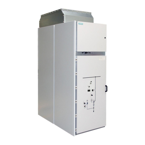
Siemens NXAIR M Operating Instructions Manual (255 pages)
Air-Insulated Switchgear
Brand:
Siemens
| Category:
Industrial Equipment
| Size: 13.64 MB
Table of Contents
1 Safety Instructions
3
Table of Contents
4
2 General Instructions
8
Five Safety Rules of Electrical Engineering
8
Hazardous Substances
8
Personal Protective Equipment (PPE)
9
Due Application
9
Qualified Personnel
9
Update of the Firmware of Protection Relays
10
3 Features
11
4 Technical Data
12
Complete Switchgear
12
Basic Prescriptions and Standards
12
Electromagnetic Compatibility - EMC
13
Rating Plates
13
IAC Classification
13
Panel Dimensions
14
Room Planning
14
Operating Conditions
14
Vacuum Circuit-Breaker Type 3AE
15
Operating Instructions for Circuit-Breaker Type 3AE
15
5 Overview of Panel Types
16
6 Panel Design
18
Basic Design Circuit-Breaker Panel, Single-Busbar System
18
Basic Design Circuit-Breaker Panel with HV HRC Fuse
18
Basic Design Circuit-Breaker Panel, Double-Busbar System
19
7 Interlocks
20
Mechanical Interlocks for Single-Busbar System
20
Mechanical Interlocks for Double-Busbar System
21
Additional Electromagnetic Interlocks (Optional)
21
Additional Padlock Interlock (Optional)
22
Additional Key-Operated Interlock (Optional)
22
8 Accessories
23
Operating Tools
23
Service Truck
25
Service Truck Versions
25
9 Customer Support
28
Service
28
Repairs
28
Before You Call
28
Service Contact
28
10 Operating the Circuit-Breaker Panel
29
Control Elements at the Front Side of the Panel
29
Position Indicators Visible on High-Voltage Door
30
Access to Compartments
30
Opening the High-Voltage Door
30
Closing the High-Voltage Door
32
Positions of the Withdrawable Circuit-Breaker
34
Racking the Withdrawable Circuit-Breaker to Service Position
35
Racking the Withdrawable Circuit-Breaker to Test Position
37
Closing the Circuit-Breaker Electrically
40
Opening the Circuit-Breaker Electrically
41
Closing the Circuit-Breaker Manually
42
Opening the Circuit-Breaker Manually
45
Discharging the Spring Energy Store
47
Charging the Spring Manually
48
Earthing the Feeder Manually
51
Earthing the Feeder Manually
53
Removing the Low-Voltage Connector
56
Plugging on the Low-Voltage Connector
57
Taking the Withdrawable Circuit-Breaker out of the Panel
59
Inserting the Withdrawable Circuit-Breaker in a Panel
64
11 Operating the Disconnecting Panel
73
Control Elements at the Front Side of the Panel
73
Position Indicators Visible on High-Voltage Door
73
Access to Compartments
74
Opening or Closing the High-Voltage Door
74
Racking the Withdrawable Disconnector Link
74
Removing or Plugging on the Low-Voltage Connector
76
Taking the Withdrawable Disconnector Link out of a Panel or Inserting in a Panel
76
Earthing or De-Earthing the Feeder
76
12 Operating the Metering Panel
77
Control Elements at the Front Side of the Panel
77
Position Indicators Visible on High-Voltage Door
77
Access to Compartments
78
Opening or Closing the High-Voltage Door
78
Racking the Withdrawable Metering Part
78
Removing or Plugging on the Low-Voltage Connector
78
Taking the Withdrawable Metering Part out of a Panel or Inserting in a Panel
79
Replacing Protection Fuse-Links
79
13 Operating the Circuit-Breaker Panel with HV HRC Fuse
83
Control Elements at the Front Side of the Panel
83
Position Indicators Visible on High-Voltage Door
84
Access to Compartments
84
Opening or Closing the High-Voltage Door
84
Racking the Withdrawable Part
84
Closing or Opening the Circuit Breaker / Fuse Combination
85
Discharging or Charging the Closing Spring
85
Earthing or De-Earthing the Feeder Manually
85
Removing the Low-Voltage Connector
85
Plugging on the Low-Voltage Connector
87
Taking the Withdrawable Circuit-Breaker / Fuse Combination out of a Panel or Inserting in a Panel
89
Replacement of HV HRC Fuse-Links
89
14 Operating the Circuit-Breaker Panel for Double-Busbar System
99
Position Indicators Visible on High-Voltage Door, Panel a
101
Position Indicators Visible on High-Voltage Door, Panel B
101
Access to Compartments
101
Opening or Closing the High-Voltage Door
102
Positions of the Withdrawable Circuit-Breaker
102
Racking the Withdrawable Circuit-Breaker
102
Closing or Opening the Circuit-Breaker
102
Discharging or Charging the Closing Spring
102
Earthing or De-Earthing the Feeder
103
Removing or Plugging on the Low-Voltage Connector
103
Taking the Withdrawable Part out of a Panel or Inserting in a Panel
103
15 Operating the Removable Voltage Transformers
104
Opening or Closing the High-Voltage Door
104
Racking the Removable Voltage Transformers to Service Position
105
Racking the Removable Voltage Transformers to Test Position
109
Taking the Removable Voltage Transformers out of the Panel
113
Inserting the Removable Voltage Transformers in a Panel
117
Replacing Protection Fuse-Links
122
16 Verifying Safe Isolation from Supply
125
Application of Voltage Indicators
125
Overview of Voltage Indicating Systems
125
LRM System Overview
126
Verifying LRM-ST Voltage Indicator
127
Verifying Safe Isolation from Supply with the LRM Device System
128
CAPDIS and VOIS Systems Overview
129
Verifying Safe Isolation from Supply with the CAPDIS or VOIS Device System
132
Supplier Information
132
17 Earthing and De-Earthing the Busbar System
133
Earthing the Busbar System Manually
133
Earthing the Busbar System Manually
138
18 Operating the Shutters
143
Operating the Shutter to the Busbar Compartment in the Switching-Device Compartment
143
Operating the Shutter to the Connection Compartment in the Switching-Device Compartment
146
19 Accessing the Connection Compartment through the Front
150
Preparations before Accessing the Connection Compartment
150
Accessing the Connection Compartment through the Switching-Device Compartment
152
Installing the Vertical Partition in the Switching-Device Compartment
153
Accessing the Connection Compartment through the Switching-Device Compartment in Panel Versions with Ventilation System
157
Installing the Vertical Partition and the Ventilation Duct in the Switching-Device Compartment
162
Accessing the Connection Compartment through the Switching-Device Compartment in Panel Versions with Voltage Transformer Compartment
168
Installing the Bushing Plate, the Vertical Partition and the Voltage Transformer Compartment in the Switching-Device Compartment
172
20 Accessing the Connection Compartment through the Rear
177
Accessing the Connection Compartment through the Rear Side of the Panel
177
Installing the Rear Wall on the Connection Compartment
180
Accessing the Connection Duct through the Rear Side of the Panel
183
Installing the Rear Walls on the Connection Duct
186
21 Key-Operated Interlocks
189
Key-Operated Interlocks for the Busbar Earthing Switch
191
22 Fitting the Earthing Device
193
Design, Application and Inspection of the Earthing Accessories
193
Connecting the Earthing Device
194
Removing the Earthing Device
201
23 Panels with Motor Operating Mechanism Control
205
Overview of Functionality
205
Opening the Control Door
209
Closing the Control Door
210
Selecting Manual Operation for Racking
211
Selecting Electrical Operation for Racking
213
Selecting Interlocking
214
Racking the Withdrawable Circuit-Breaker to Service Position Manually
217
Racking the Withdrawable Circuit-Breaker to Service Position Electrically
220
Racking the Withdrawable Circuit-Breaker to Test Position Manually
221
Racking the Withdrawable Circuit-Breaker to Test Position Electrically
225
Opening the Circuit-Breaker Manually
226
Closing the Circuit-Breaker Manually
227
Charging / Discharging the Spring Energy Store Manually
228
Earthing / De-Earthing the Feeder Manually
230
Earthing / De- Earthing the Feeder Electrically
232
Earthing / De-Earthing the Busbar System Manually
233
Earthing / De-Earthing the Busbar System Electrically
233
Further Operating Options
234
Technical Data / Operating Times
235
Fault Indication and Fault Evaluation
236
24 Panel Heater
237
Heater Versions
237
Mechanical Temperature Controller
237
Electronic Temperature and Humidity Controller
238
Applications for Temperature Controller
238
25 Service Information
240
General Maintenance
240
Time Schedule for Maintenance Measures
240
Visual Inspection
241
Preventive Maintenance
242
Lubricants to be Used
244
Overpressure Sensors (Optional), Function Test
245
Switchgear Extension
248
Spare Part Orders
248
Replacement of Panels and Components
248
Disposal
248
26 Trouble Shooting
249
Panels
249
27 Index
251
Advertisement
Advertisement
Related Products
Siemens NXAIR
Siemens SINUMERIK ONE NCU 1760
Siemens SIMATIC NET S7-300
Siemens SIMATIC NET C7-300
Siemens SIMATIC NET S7-400H
Siemens SIMATIC NET S7-4100
Siemens N 535D51
Siemens SINUMERIK ONE NCU 1750
Siemens NXAIR P
Siemens NXAirS
Siemens Categories
Industrial Equipment
Controller
Control Unit
Oven
Washer
More Siemens Manuals
Login
Sign In
OR
Sign in with Facebook
Sign in with Google
Upload manual
Upload from disk
Upload from URL