Sign In
Upload
Manuals
Brands
Siemens Manuals
Laboratory Equipment
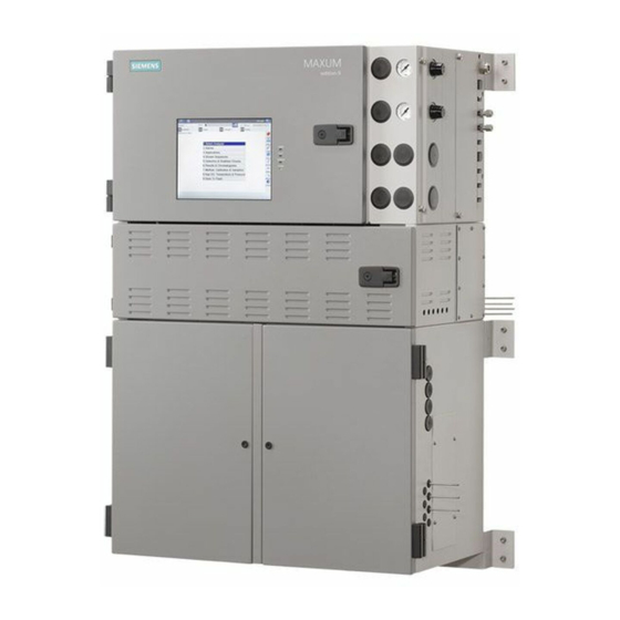
Maxum II
Siemens Maxum II Manuals
Manuals and User Guides for Siemens Maxum II. We have
5
Siemens Maxum II manuals available for free PDF download: Reference Manual, Manual, Service Manual, Installation Manual
Siemens Maxum II Reference Manual (100 pages)
Brand:
Siemens
| Category:
Laboratory Equipment
| Size: 38.46 MB
Table of Contents
Table of Contents
3
1 Analyzer Overview
7
Introduction
7
Analyzer Specific Documents
8
Parts of the Maxum II
8
Isothermal Oven
9
Switching and Sampling Valves
10
Operator Controls
11
2 Electronic Compartment Component Descriptions and Maintenance Procedures
13
Power Supplies
13
Power System Module
13
Replacement Procedure
15
Power Entry and Control Module
18
PECM Overview
18
Feature Additions
19
PECM Functions
20
AC Input and Distribution
20
Oven Temperature Control
21
Communication and Power Distribution
22
Onboard Solid State Relays
23
Oven Functions
24
Electronic Enclosure Environment
26
Replacement Procedure
28
Troubleshooting
28
Removing the PECM
30
Installing the New PECM
31
System Controller Version 2.1 (SYSCON2.1)
32
Description
32
Mechanical
33
SYSCON2.1 Components
34
Communication and Control Board (CAC3)
34
CAC3 Status Indicator Leds
35
Sib
36
Ethernet Port Expansion
44
Maintenance Overview
48
Service Procedures
48
Replacing the Lithium Battery on the SYSCON Module Introduction
53
Procedure
53
Analog and Digital IO
54
IO Card Common Features
55
Digital IO Card
58
Analog IO Board
59
Analog and Digital IO Board
60
Detector Personality Modules
61
DPM Types
61
Base3 Detector Personality Module (DPM)
61
Replacing a Base3Dpm
66
Intrinsically-Safe Thermal Conductivity DPM (IS-TCD3)
68
Replacing an IS-TCD DPM
70
Replacing a TC-DPM
71
Sensor Near Electronics (SNE) Software
72
Solid State Relay Module
74
Solenoid Valves
76
Solenoid Valve Control Module (SVCM)
76
Replacing a Solenoid Valve
80
Electronic Pressure Control Module
81
EPC Module Description
81
Replacing an EPC Module
83
Color Touchscreen
85
Description
85
Maintenance Overview
85
Replacement Procedures
86
3 Specifications
93
Index
99
Advertisement
Siemens Maxum II Manual (86 pages)
PD PA AP. General Maintenance
Brand:
Siemens
| Category:
Measuring Instruments
| Size: 2.66 MB
Table of Contents
Table of Contents
3
1 Introduction
5
Analyzer Specific Documents
5
2 Safety Notes
7
Approved Use
7
Qualified Personnel
8
3 System Functions
9
Chromatography Overview
9
Functions
10
Figure 3-1 Example Applet
10
Analyzer Operation
13
Figure 3-2 Operational Block Diagram (Maxum II Airless Airbath Model Shown)
14
Data Communication
17
Figure 3-3 Data Communication Paths
17
Figure 3-4 Identification Number
18
4 General Maintenance and Troubleshooting
19
Analyzer Status Indicators
19
Operator Controls
19
LED States Inside the Electronics Cabinet
21
Base3Dpm Status Indicator Leds
21
Figure 4-1 Base3Dpm Status Leds
21
SIB3 Leds
22
Figure 4-2 SIB3 Leds and Switches
22
PECM Leds
25
Modular Oven Model PECM-DC LED Locations
26
Leak Testing
26
General Analyzer Shutdown Procedure
27
General Analyzer Startup Procedure
27
Procedure
28
Accessing the Bootloader
30
Alarm Codes, Descriptions, and Suggested Actions
31
Alarms 301 - 324
31
Alarms 330 through 359 SNE Communication
33
Alarms 360 - 399
35
Alarms 400 - 562
37
Alarms 671 - 699
41
Alarms 700 - 737
43
Alarms 801 - 999
45
Alarms 1002 - 1128
47
Alarms 1317 - 1319
52
Alarms 1617 - 1697 Pecm Errors
53
Alarms 1917 - 2005 DPM TCD
55
Alarms 2217 - 2306 DPM FID
58
Alarms 2500 - 2577 Access Bus Driver Errors
62
Alarms 2817 - 2904 DPM Temperature
67
Alarms 3117 - 3204 EPC
69
Alarms 3401 - 3454 TFTP
70
Alarms 3500 - 3528 Advance
71
Alarms 3718 - 3804 SNE I/O
72
Alarms 4001 - 4124 Ezchrom
75
Alarms 4217 - 4320 CAN Bridge
77
Alarms 4525 - 5220 Advance TC
79
Alarms 10000 - 11536 Microsam
81
Appendix A - Contact Information
83
Index
85
Siemens Maxum II Manual (68 pages)
Process Gas Chromatograph
Brand:
Siemens
| Category:
Industrial Equipment
| Size: 8.71 MB
Table of Contents
Table of Contents
3
General Information for the User
7
Figure 1-1 Reference of Hardware (MAA) to Applicable Sections of this Manual
8
Figure 1-2 Reference of Hardware (MMO) to Applicable Sections of this Manual
8
Contacts
10
Approved Use
11
Qualified Personnel
11
Applicable Standards and Regulations
12
Safety Protection Principles
13
Intrinsically Safe Devices
14
Safety Systems - Purging
17
Purging Overview
17
Electronics Purging System (Without Automatic Purge Unit)
18
Overview
18
Figure 2-1 Electronics Pressurization System (Type Py) for Airbath/Airless Oven Model (New Pressure Relief Valve Configuration)
18
Figure 2-2 Electronics Pressurization System (Type Py) for Airbath/Airless Oven Model (Old Pressure Relief Valve Configuration)
19
Figure 2-3 Electronics Pressurization System (Type Py) for Modular Oven Model
19
Instrument Air Inlet and Regulator
20
Figure 2-4 Instrument Air Inlet and Pressure Regulator
20
Fast Purge Switch
21
Figure 2-5 Fast Purge Switch (Shown in the off Position)
22
Purge Control Module
23
SYSCON or CIM and Purge Alarm Light
23
Figure 2-6 Purge Control Module
23
Figure 2-7 Purge Alarm Indicator Lamp
23
Pressure Sensor and Atmospheric Pressure Reference
24
Figure 2-8 Pressure Sensor on PECM Board
24
Figure 2-9 Atmospheric Pressure Reference for Purge
24
Fast Purge Pressure Relief Valve
25
Figure 2-10 Pressure Relief Valve for PY Purge
25
Electronics Purging System (with Automatic Purge Unit)
26
Overview
26
Figure 2-11 APU System Component Layout (Modular Oven Model)
26
Purge Air Inlet and Regulator
27
Figure 2-12 Purge Air Inlet and Pressure Regulator
27
Proportional Valve
28
Automatic Purge Control Unit
28
Maintenance Switch
29
Exhaust Diffuser
30
Signal Disconnect Relay
31
Maintenance Considerations for Purged Systems
32
Safety Systems - Oven
35
General Oven Information
35
Isothermal Air Bath Oven Heater System (Single and Split)
36
Purging
36
Temperature Control
37
Programmed Temperature Air Bath Oven Heater System (Split)
38
Isothermal Airless Oven Heater System (Split)
39
Maintenance Considerations for Air Bath and Airless Ovens
41
Modular Oven Heater System
42
Maintenance Considerations Modular Ovens
43
Valves, Detectors, and External Systems
45
Heated Siemens Liquid Injection Valve (SLIV)
45
SLIV Functional Description
45
SLIV Maintenance Considerations
46
Detectors
47
Detector Functional Descriptions
47
Detector Maintenance Considerations
48
Air Treater
52
Air Treater Functional Description
52
Air Treater Maintenance Considerations
53
Methanator
53
Methanator Functional Description
53
Methanator Maintenance Considerations
55
Safe Operation
57
Maintenance Panel Functional Description
57
Maintenance Considerations for Maintenance Panel
58
Color Touchscreen Display Functional Description
58
Maintenance Considerations for Control Interface Module Display
59
Steps for Safe Startup of Maxum II
60
Overview
60
Procedure
60
Glossary
63
Advertisement
Siemens Maxum II Installation Manual (52 pages)
Brand:
Siemens
| Category:
Laboratory Equipment
| Size: 7.94 MB
Table of Contents
Table of Contents
3
Installation Overview
7
Safety Notes
9
Read the Safety Manual First
9
Analyzer Environment
9
Figure 2-1 Typical Analyzer Shelter
9
Hazardous Gasses
10
Location
10
Security Information
11
Approved Use
12
Qualified Personnel
12
Installation Steps
13
Custom Application Drawing Package
13
Considerations for Pulsed Discharge Detector Installation
13
Receiving a Crated Analyzer
14
Figure 3-1 Crated Analyzer
14
Figure 3-2 Uncrating Details
15
Mounting the Analyzer
16
Figure 3-3 Using a Lift to Install an Analyzer
16
Pre-Installation Requirements
17
Wall Mounting Units
17
Mounting and Powering an Air Treater
18
Figure 3-4 Example Maxum II Outline Drawing (Air-Bath or Airless Oven on Left and Modular Oven on Right)
18
Cable Connections
19
Figure 3-5 Simplified Cable Connection Diagram - no APU
19
Figure 3-6 Simplified Cable Connection Diagram - with APU
19
Protective Earth Ground
20
Cable Connection Using Steel Conduit System
20
Figure 3-7 Protective Earth Ground Symbol
20
Power Connections
21
Air Bath or Airless AC Input and Fuses
22
Modular Oven Model Power Connections
23
Customer Supplied Components
25
Installing AC Power
25
Signal Cables
26
Automatic Purge Unit
27
Utility Gas Supply Installation
28
Air Supply
28
Minimum Air Pressure
28
FID Air Supply
29
Calibration Standard Supply
29
Detector Flame Fuel Supply
29
Carrier Supply
30
Table 3-1 Regulator Assemblies
30
Heat Tracing
31
Sampling System Installation
31
Heat Tracing
33
Sample Wetted Parts
33
Returning Samples to the Process Stream
33
Final Analyzer Connections
34
IO Wiring
35
Tubing Connections
35
Initial Startup Procedures
37
Inspect the Electronics Cabinet
37
Preparing and Inspecting the Oven
38
Establish Utility Gas Flows
40
Enable Power to the Maxum II
40
Leak Check the Column Oven Connections
40
Check Operation of Oven Heaters
41
Check Flows and Pressures at Operating Temperature
42
Prepare Flame Detectors if Present
43
Establish Sample Flow to the Maxum II
43
Establish Communications with GCP
44
Run Chromatograms and Make Method Adjustments if Necessary
45
Calibrate the Maxum II
45
Run the Maxum II on Process Fluid
47
Check for Proper Reporting of Results
47
Appendix A - PECM LED Interpretation
49
Appendix B - Change Log
51
December 2019 Changes
51
Siemens Maxum II Service Manual (58 pages)
Brand:
Siemens
| Category:
Other
| Size: 9.52 MB
Table of Contents
Table of Contents
3
1 Detector Overview
5
DPM Types
5
2 Thermal Conductivity Detector
7
Intrinsically Safe Thermal Conductivity DPM
8
Replacing TCD Components
11
Replace TCD Thermistor Beads/Filaments Introduction
11
Procedure to Replace Thermistor Beads
12
Replacing an IS-TCD DPM
13
TCD Specifications
15
3 Flame Photometric Detector
17
Upgrade Description
21
Intended Users
21
Safety and Certification Information
21
Procedure - Upgrade FPDI to FPDII
22
Base3 Detector Personality Module (DPM)
23
Base3Dpm Status Indicator Leds
28
Replacing a Base3Dpm
29
FPD Specifications
30
4 Flame Ionization Detector
31
FID Maintenance Considerations
32
Intended Users
32
Safety and Certification Information
32
Available FID Repair Kits
32
Purge Coil and Filter
33
Replacing the FID Mesh Filter
33
Procedure to Replace Mesh Filter
35
Replacing the FID Quartz Jet
36
Procedure to Replace Quartz Jet
36
Replacing the FID Igniter
37
Procedure - Parts
37
Procedure - Removing the Detector
38
Procedure - Igniter Replacement
42
Procedure - Reinstalling the Detector
46
FID Specifications
47
Filament Detector
48
Replacing the Filaments
50
Methanator
51
Methanator Function
51
Purged Methanator
52
Explosion-Proof Methanator
53
Methanator Specifications
53
Methanator Maintenance Considerations
54
Air Treater
55
Air Treater Maintenance Considerations
55
Air Treater Specifications
56
5 Valco Pulse Discharge Detector
57
PDD Specifications
57
Advertisement
Related Products
Siemens Simatic MV220
Siemens Maxum II PD PA AP
Siemens MAGNETOM Skyra
Siemens SITRANS MAG 1100 F
Siemens SITRANS MAG 3100P
Siemens SITRANS F C MASSFLO MASS 2100
siemens SITRANS F M MAG 5000 SV
Siemens MAG 5000 CT
Siemens MAMMOMAT Balance
Siemens MAG 3100 P
Siemens Categories
Industrial Equipment
Controller
Control Unit
Oven
Washer
More Siemens Manuals
Login
Sign In
OR
Sign in with Facebook
Sign in with Google
Upload manual
Upload from disk
Upload from URL