Sign In
Upload
Manuals
Brands
Siemens Manuals
Controller
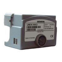
LME39. 2 Series
User Manuals: Siemens LME39. 2 Series Burner Controls
Manuals and User Guides for Siemens LME39. 2 Series Burner Controls. We have
1
Siemens LME39. 2 Series Burner Controls manual available for free PDF download: Basic Documentation
Siemens LME39. 2 Series Basic Documentation (73 pages)
Gas burner controls
Brand:
Siemens
| Category:
Controller
| Size: 1.63 MB
Table of Contents
Supplementary Documentation
3
Supplementary Documentation
2
Table of Contents
3
1 Safety Notes
7
Warning Notes
7
Engineering Notes
7
Mounting Notes
7
Installation Notes
8
Figure 1: Correct Wiring of Neutral Conductors
8
Connection BCI Via Integrated Jack RJ11
9
Figure 2: Connection Display and Operating Unit AZL2
9
Electrical Connection of Flame Detectors
10
Figure 3: Connection BC Interface OCI410
10
Figure 4: Connection Interface OCI400
10
Commissioning Notes
11
Standards and Certificates
12
Life Cycle
13
Disposal Notes
13
2 Makeup of System/Description of Functions
13
Use
13
Features
13
3 Basic Unit
14
Time Parameters
14
Figure 5: Example: Modulating Gas Burner
14
Indication and Diagnostics
15
Communication/Parameterization
15
4 Type Summary (Other Types on Request)
16
5 Accessories (to be Ordered Separately)
18
Connection Accessories for Small Burner Controls
18
Service Tools
18
Display and Operating Units
19
Flame Detector
19
Actuators
20
Others
21
6 Technical Data
22
General Unit Data
22
Signal Cable AGV50
23
Environmental Conditions
23
Flame Supervision with Ionization Probe
24
Measuring Circuit
24
Figure 6: Measuring Circuit: Ionization Probe
24
Flame Supervision with Agq3.Xa27 and Flame Detector QRA
25
Figure 7: Connection Diagram Agq3.Xa27
25
Figure 8: Measurement Made at the Flame Detector QRA
25
7 Functions
26
Preconditions for Burner Startup
26
Undervoltage
26
Controlled Intermittent Operation
26
Control Sequence in the Event of Fault
27
Resetting the Burner Control
27
Limitation of Repetitions (Can be Parameterized)
28
8 PC Software ACS410
28
Duty of PC Software
28
9 Operation, Indication, Diagnostics
29
Operation
29
Operational Status Indication
29
Diagnostics of Cause of Fault
30
Figure 9: Diagnostics of Cause of Fault
30
10 Inputs and Outputs/Internal Connection Diagram/Program Sequence of LME39.100
32
Program Sequence
32
Figure 10: Program Sequence
32
Inputs and Outputs/Internal Connection Diagram
33
Figure 11: Internal Diagram
33
Application Examples
34
Figure 12: Application Examples LME39.100
34
Application LME39.100
35
Figure 13: Application Examples with LDU11
35
11 Inputs and Outputs/Internal Connection Diagram/Program Sequence of LME39.400
36
Program Sequence
36
Figure 14: Program Sequence
36
Inputs and Outputs/Internal Connection Diagram
37
Application Example
37
Figure 15: Internal Diagram
37
Figure 16: Only for Burners with Fan Control Via Auxiliary Contactor with Air Pressure
37
12 Legend
38
13 Dimensions
39
Lme39
39
Figure 17: Dimensions LME39
39
Lme39
40
Ancillary Unit Agq3.Xa27
40
Figure 18: Dimensions LME39
40
Figure 19: Dimensions Agq3.Xa27
40
14 Operation Via the AZL2
41
Description of the Unit/Display and Buttons
41
Figure 20: Description of the Unit/Display and Buttons
41
Meaning of Symbols on the Display
42
Special Functions
42
Manual Lockout
42
Figure 21: Meaning of Display
42
15 Operation
43
Normal Display
43
Display in Standby Mode
43
Display During Startup/Shutdown
43
Display of Program Phases
43
List of Phase Displays
43
Display of Operating Position
44
Fault Status Messages, Display of Errors and Info
44
Display of Errors (Faults) with Lockout
44
Reset
44
16 Menu-Driven Operation
45
Assignment of Levels
45
Figure 22: Assignment of Levels
45
17 Info Level
46
Display of Info Level
46
Figure 23: Info Level
46
Display of Info Values
47
Identification Date
47
Identification Number
47
Identification of Burner
48
Number of Startups Resettable
49
Total Number of Startups
50
End of Info Level
50
18 Service Level
51
Display of the Service Level
51
Display of Service Values
52
Error History
52
Mains Voltage
52
Intensity of Flame
52
End of Service Level
52
19 Parameter Level
53
Entering the Password
54
Changing the Heating Engineer's Password
56
Changing the Oem's Password
58
20 Operating Variants of the Parameters
59
Parameters Without Index, with Direct Display
59
Example of Parameter 226 (Preignition Time) on the Parameter Level
59
Parameters Without Index, with no Direct Display
61
Example of Parameter 224 (Max. Time until Air Pressure On) on the Parameter Level
61
Parameters with Index, with or Without Direct Display
63
Example of Parameter 701 (Actual Error) on the Service Level
63
21 Error Code List
65
22 Parameter List
66
List of Figures
72
Advertisement
Advertisement
Related Products
Siemens LME39 Series
Siemens LME39. 1 Series
Siemens LME39.100C1
Siemens LME39.100C2
Siemens LME39.400C1
Siemens LME39.400C2
Siemens LME21.130A2
Siemens LME44.057A1
Siemens LME75
Siemens LME23.331A2
Siemens Categories
Industrial Equipment
Controller
Control Unit
Oven
Washer
More Siemens Manuals
Login
Sign In
OR
Sign in with Facebook
Sign in with Google
Upload manual
Upload from disk
Upload from URL