Sign In
Upload
Manuals
Brands
Siemens Manuals
Measuring Instruments
FCC2003-A1
Siemens FCC2003-A1 Manuals
Manuals and User Guides for Siemens FCC2003-A1. We have
1
Siemens FCC2003-A1 manual available for free PDF download: Product Data
Siemens FCC2003-A1 Product Data (302 pages)
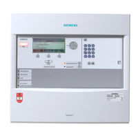
Fire detection system
Brand:
Siemens
| Category:
Measuring Instruments
| Size: 11.4 MB
Table of Contents
Table of Contents
3
1 About this Document
13
Applicable Documents
14
Technical Terms
14
History of Changes
15
2 Safety
17
Safety Instructions
17
Safety Regulations for the Method of Operation
18
Standards and Directives Complied with
20
CPD Conformity and Firmware Version
20
Release Notes
21
3 Power Supply (70 W) FP2001-A1
22
Description
22
Views
23
Pin Assignments
23
X1 Mains Connection
23
X2 Monitoring Signals
24
Indicators
24
Technical Data
25
4 Power Supply (150 W) SV 24V-150W-A4
26
Description
26
Views
27
Pin Assignments
28
X1 Mains Connection
28
X8 Output Voltage
28
X11 Monitoring Signals
29
Parallel Switching of Two Supply Units
30
Indicators
31
Technical Data
32
5 Power Supply (150 W) SV 24V-150W-A5
34
Description
34
Views
35
Pin Assignments
36
X1 Mains Connection
36
X8 Output Voltage
36
X11 Monitoring Signals
37
Parallel Switching of Two Supply Units
38
Parallel Switching of Three Supply Units
40
Indicators
41
Technical Data
42
6 Fire Terminal Board FTI2001-A1
44
Description
44
Views
45
Pin Assignments
46
X1 Supply
46
X5 Supply Output
47
X6/X7 Supply Input 2/1
48
Indicators
49
Adjustment Elements
50
Technical Data
50
7 Periphery Board (2 Loops) FCI2002-A1
51
Description
51
Views
52
Pin Assignments
53
X12 Detector Line Loop 2
53
X11 Detector Line Loop 1
54
X9 Configurable Inputs/Outputs 5
54
X8 Configurable Inputs/Outputs 1
55
X7 RT Alarm and RT Fault Changeover Contacts
55
X6 Horn, Alarm and Fault Monitored Outputs
56
X1 Supply
57
Indicators
57
Adjustment Elements
59
Technical Data
60
8 Periphery Board (4 Loops) FCI2004-A1
63
Description
63
Views
64
Pin Assignments
66
X12 / X22 Detector Line Loop 2 (Module 2/3)
66
X11 / X21 Detector Line Loop 1 (Module 2/3)
66
X8 Configurable Inputs/Outputs 1
67
X7 RT Alarm and RT Fault Changeover Contacts
68
X6 Alarm and Fault Monitored Outputs
69
X5 Monitored Horn Outputs 1 and 2
69
X1 Supply
70
Indicators
70
Adjustment Elements
73
Technical Data
73
9 Loop Extension FCI2003-A1
76
Description
76
Views
76
Pin Assignments
77
X13 Connection Loop 3
77
X14 Connection Loop 4
77
Technical Data
78
10 Operating Unit with PMI & Mainboard FCM2004
79
Description
79
View of PMI & Mainboard
80
Indicators
81
Adjustment Elements
81
Technical Data
82
11 Operating Unit with PMI & Mainboard FCM2027
83
Description
83
View of PMI & Mainboard
84
Indicators
85
Adjustment Elements
86
Technical Data
87
12 LED Indicator (Internal) FTO2002-A1
88
Description
88
Views
89
Adjustment Elements
90
Technical Data
90
13 RS232 Module (Isolated) FCA2001-A1
91
Description
91
Views
91
Pin Assignments
92
X3 Dte-Host
92
Technical Data
93
14 RS485 Module (Isolated) FCA2002-A1
94
Description
94
Views
94
Pin Assignments
95
X2 Connector
95
Technical Data
96
15 Network Module (SAFEDLINK) FN2001-A1
97
Description
97
Views
98
Pin Assignments
98
Connector X3
98
Indicators
99
Technical Data
100
16 Network Module (SAFEDLINK, CC) FN2010-A1
101
Description
101
Views
102
Indicators
102
Technical Data
103
17 Fiber Optic Network Module FN2006 / FN2007
104
Description
104
Views
105
Pin Assignments
105
Power a and Power B Sockets
105
EF1/EF2 Sockets for SAFDLINK Networking
106
Fiber Optic Cable Connection
108
Indicators
109
Technical Data
109
18 Repeater (SAFEDLINK) FN2002-A1
111
Description
111
Views
112
Pin Assignments
113
Connector X3
113
Plug X2
113
Indicators
114
Technical Data
114
19 Interface Module DL485/13-XX-ST-SBT
115
Description
115
Views
116
Pin Assignments
117
Terminal Strip Supply
117
Terminal Strip Data Line
117
Fiber Optic Cable Connection
118
Indicators
119
Adjustment Elements
119
Technical Data
120
20 Ethernet Switch (MM) FN2008-A1
121
Description
121
Views
122
Pin Assignments
123
Connector Strip for Supply
123
Connector Strip for Detector Contact
123
Connecting Optical Ethernet
123
Indicators
125
Adjustment Elements
126
Set Button
126
C-Plug (Option)
127
Technical Data
128
21 Safety Module (Firewall) FN2009-A1
129
Description
129
Views
130
Pin Assignments
131
Connector Strip for Supply
131
Connector Strip for Detector Contact
131
Indicators
131
Adjustment Elements
132
Technical Data
134
22 Card Cage (2 Slots) FCA2007-A1
135
Description
135
Views of Card Cage (2 Slots)
136
Pin Assignments
137
X9 Supply
137
X11
137
Technical Data
138
23 Card Cage (5 Slots) FCA2008-A1
139
Description
139
Views of Card Cage (5 Slots)
140
Pin Assignments
141
X9 Supply
141
X11
142
Technical Data
142
24 Connection Module (Card Cage) FCA2006-A1
143
Description
143
Views
143
Technical Data
144
25 Line Card (Fdnet/C-NET) FCL2001-A1
145
Description
145
Views
146
Pin Assignments
147
Connection Terminals of Line Card (Fdnet/C-NET) in Card Cage
147
Indicators
148
Adjustment Elements
148
Technical Data
149
26 Line Card (Collective) FCL2002-A1
150
Description
150
Views
151
Pin Assignments
152
Connection Terminals of Line Card (Collective) in Card Cage
152
Indicators
153
Adjustment Elements
153
Technical Data
153
27 Line Card (Ms9I) FCL2003-A1
154
Description
154
Views
155
Pin Assignments
156
Connection Terminals of Line Card (Ms9I) in Card Cage
156
Indicators
157
Adjustment Elements
157
Technical Data
158
28 O Card (Programmable) FCI2008-A1
159
Description
159
Views
160
Pin Assignments
161
Connection Terminals for the I/O Card (Programmable) in the Card Cage161
161
Indicators
162
Adjustment Elements
163
Technical Data
164
29 O Card (Horn/Monitored) FCI2009-A1
165
Description
165
Views
166
Pin Assignments
167
Connection Terminals for the I/O Card (Horn/Monitored) in the Card Cage
167
Indicators
169
Adjustment Elements
169
Technical Data
170
30 O Card (RT) FCI2007-A1
171
Description
171
Views
172
Pin Assignments
173
Connection Terminals for the I/O Card (RT) in the Card Cage
173
Indicators
176
Adjustment Elements
177
Technical Data
178
31 Sounder Module FCA2005-A1
180
Description
180
Views
181
Pin Assignments
182
Cascading of Two Sounder Modules
182
X3 Sounder 3 and 4 Outputs
182
X2 Sounder 1 and 2 Outputs
183
X1 Supply Input and Sounder Input from the Periphery Board
184
Indicators
184
Technical Data
184
32 Processor Unit (19", FC2080) FCC2002-A1
186
Description
186
View of Card Cage (CPU) FCC2003-A1
187
Pin Assignments
188
X11/X12 Connection Terminals for SDL1/SDL2
188
X10 Connector Terminal for Supply
189
X41 / X42 / X51 / X52 Connection Terminals for Module Bus Cards
190
X14 SER_OPT1, RS485 Connection Terminal
190
X13 SER_OPT2, RS232 Connection Terminal
191
Technical Data
191
33 Card Cage (CPU) FCC2003-A1
192
34 CPU Card (FC2080) FCC2004-A1
193
Description
193
Views
194
Indicators
195
LED Matrix Display
196
Adjustment Elements
200
Technical Data
200
35 Communication Card (FC2080) FCC2005-A1
201
Description
201
Views
202
Indicators
203
Technical Data
204
36 Communication Card (FG2020-D1) FCC2008-D1
205
Description
205
Views
206
Indicators
207
Technical Data
208
37 Housing for Wall Mounting
209
Description
209
Views
209
Housing (Eco)
210
Housing (Standard)
211
Housing (Comfort)
212
Housing (Large Extension)
213
Housing (Large)
214
Operating Unit Carrier
215
Cover Cap
216
Technical Data
217
38 Housing (19", Pedestal Cabinet) FH2080-AA
218
Description
218
Views
219
Housing (19" Pedestal Cabinet)
219
Carrier (19", Card Cage)
220
Carrier (19", Option)
221
Battery Bracket (19") FHA2021-A1
222
Technical Data
222
39 Floor Repeater Terminal FT2010
223
Description
223
Views
224
Pin Assignments
224
X101 Detector Line and External Supply
224
Adjustment Elements
225
Technical Data
226
40 Floor Repeater Display FT2011
227
Description
227
Views
228
Pin Assignments
228
X101 Detector Line and External Supply
228
Adjustment Elements
229
Technical Data
230
41 MIMIC Display Driver FT2001-A1
231
Description
231
Views
232
Pcb
232
Carrier
233
Pin Assignments
233
X12 Driver Outputs 25
233
X11 Driver Outputs 1
234
X8 Monitoring External Supply and Operating LED
235
X5 Expanded Periphery
236
X1 Detector Line and External Supply
236
Indicators
237
Adjustment Elements
237
Technical Data
238
42 Event Printer FTO2001-A1
239
Pin Assignments
239
Connection on Printer Side
239
Connection on Station Side
239
43 Fire Brigade Periphery Module FCI2001-D1 [DE]
241
Description
241
Views
242
Pin Assignments
243
X6 Intrusion Detection System / Local Alarm / Identification Lamp
243
X5 Fire Department Key Depot
243
X4 Remote Transmission /Release Element
244
X2 Fire Department Operating Panel / X3 Fire Department Operating Panel
245
Indicators
246
Technical Data
247
44 EVAC-NL Operating Unit FTO2007-N1
249
Description
249
Views
250
Pin Assignments
251
Indicators
253
Adjustment Elements
254
Technical Data
255
45 EVAC-NL Connector Board FTI2002-N1 [NL]
256
Description
256
Views
257
Pin Assignments
258
Cable Length and Cable Resistance
260
X1 Supply
261
X2 LED MIMIC Display
262
X3 LED MIMIC Display
264
X5 MIMIC Display Operation
266
Technical Data
268
46 EVAC-NL MIMIC Display Driver FT2003-N1 [NL]
269
Description
269
Views
270
FTO2007-N1 View
270
FTI2002-N1 View
271
Pin Assignments
272
Cable Length and Cable Resistance
272
EVAC-NL Connector Board FTI2002-N1
274
X1 Supply
274
X2 LED MIMIC Display
275
X3 LED MIMIC Display
277
X5 MIMIC Display Operation
279
Indicators
281
Adjustment Elements
282
Technical Data
283
47 RT Interface FCI2005-N1 [NL]
284
Description
284
Views
285
Pin Assignments
286
X1 Switching Contacts Relays 1
286
X2 Switching Contacts Relays 6
287
X3 Relay 11 + 12 Switching Contacts
287
X4 Relay Supply Vsys+ and Relay Coils 1
288
X5 Relay Supply Vsys+ and Relay Coils 6
288
X6 Relay Coils 11
288
X8 Relay 14 Switching Contacts
289
X7 Relay 13 Switching Contacts
289
Connection of Cable Tree to Periphery Board
289
Indicators
290
Adjustment Elements
291
Technical Data
292
48 RT Interface FCI2006-C1 [CH]
293
Description
293
Views
294
Pin Assignments
295
X15 Terminal Strip
295
Connection of Cable Tree to Periphery Board
296
Indicators
297
Adjustment Elements
297
Technical Data
298
49 FBA Terminal FTO2004-C1 [CH]
299
Description
299
Views
300
Indicators
300
Technical Data
301
Advertisement
Advertisement
Related Products
Siemens FCC2002-A1
Siemens FCC2004-A1
Siemens FCC2008-D1
Siemens FCC2005-A1
Siemens SITRANS FC430
Siemens FCA2001-A1
Siemens FCI2005-N1
Siemens SITRANS FC640
Siemens SITRANS FC740
Siemens SITRANS FC120
Siemens Categories
Industrial Equipment
Controller
Control Unit
Oven
Washer
More Siemens Manuals
Login
Sign In
OR
Sign in with Facebook
Sign in with Google
Upload manual
Upload from disk
Upload from URL