Sign In
Upload
Manuals
Brands
Siemens Manuals
Circuit breakers
8DJH
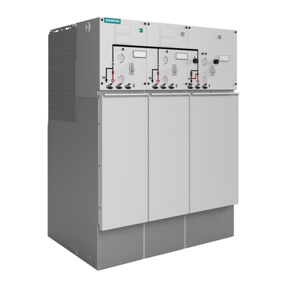
Siemens 8DJH Manuals
Manuals and User Guides for Siemens 8DJH. We have
5
Siemens 8DJH manuals available for free PDF download: Installation And Operating Instructions Manual, Operator's Manual
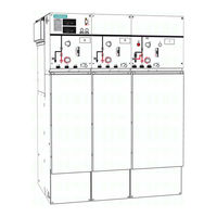
Siemens 8DJH Installation And Operating Instructions Manual (174 pages)
Medium-Voltage Switchgear
Brand:
Siemens
| Category:
Industrial Equipment
| Size: 28.25 MB
Table of Contents
Table of Contents
3
About These Instructions
6
Symbols Used
6
Instruction Concept
6
Safety Instructions
8
General Instructions
8
Due Application
8
Changes to the Product
8
Operator Commitment
8
Qualified Personnel
9
Personal Protective Equipment (PPE)
9
Security
9
Hazardous Substances
9
Description
10
Panel Types
10
Panel Design
11
Three-Position Switch-Disconnector
12
Vacuum Circuit-Breaker Type 2
13
Vacuum Circuit-Breaker Type 1.1
13
Interlocks
14
HV HRC Fuse Assembly
15
Cable Connection
16
Cable Connection for Cable Feeders, Ring-Main Feeders and Circuit-Breaker Feeders
16
Cable Connection for Transformer Feeders
17
Recommended Cable Plugs
18
Single Cable Connection with Voltage Transformer 4MT8 (Interface Type C)
20
Deep Cable Compartment Cover
21
Pressure Relief
23
Protection and Control Equipment
24
Voltage Detecting Systems
24
Ready-For-Service Indicator
24
Short-Circuit Indicators and Earth-Fault Indicators
25
Low-Voltage Compartment (Option)
25
Accessories
26
Technical Data
27
General Technical Data
27
Three-Position Switch-Disconnector
28
Three-Position Disconnector
29
Vacuum Circuit-Breaker
30
Current and Voltage Transformers
33
Classification of the Switchgear
33
Standards and Guidelines
34
Dimensions and Weights
35
Phase Sequence
37
Insulating Gas
37
Dielectric Strength and Site Altitude
37
Selection of HV HRC Fuse-Links
38
Rating Plates
46
Transport
47
Safety Instructions
47
Transport Unit
47
Checking the Delivery
47
Unloading and Transporting the Switchgear
48
Unpacking the Switchgear for Installation
50
Storage
51
Installation
53
Safety Instructions
53
Tools and Auxiliary Means
53
Cleaning Agents
53
Mounting Paste
54
Tightening Torques
54
Comments on Electromagnetic Compatibility
54
Preparing the Switchgear Room
55
Preparing the Foundation
56
Checking Service Readiness
57
Removing the Transport Eyes and Transport Blocks
58
Installing the Pressure Relief Duct for the Pressure Absorber System (IAC up to 16 Ka)
58
Installing the Base and the Pressure Relief Duct for the Pressure Absorber System (IAC up to 21 Ka)
59
Installing the Top Pressure Absorber Unit (IAC up to 21 Ka)
64
Pressure Absorber Top Unit with Low-Voltage Compartment
64
Mounting the Retaining Bracket
65
Mounting the Front Covers
65
Mounting the Lateral Parts
66
Mounting the Absorber Collar
66
Fastening the Panel to the Foundation
68
Floor Openings and Fixing Points
69
Joining the Panels
73
Lining up Panels with Busbar Coupling
75
Lining up Panels Without Busbar Coupling
79
Bolting Panels Together
80
Mounting the Busbar Termination
81
Earthing the Switchgear
85
Earthing the Extendable Switchgear
85
Earthing the Non-Extendable Switchgear
86
Interconnecting the Earthing Busbars
86
Installing the Low-Voltage Compartment
87
Installing the Metering Panel
88
Mounting Positions for Instrument Transformers in the Metering Panel Type M
88
Routing of Currents and Bars in the Metering Panel
89
Mounting the Instrument Transformers
89
Connecting the Current Transformers
91
Connecting the Voltage Transformers
92
Connecting High-Voltage Cables in the Metering Panel
95
Mounting the Spherical Connection Bolts
96
Laying Wires of Secondary Equipment
97
Mounting Earthing Accessories in the Metering Panel
98
Installing Floor Plates in Metering Panels
100
Electrical Connections
102
Safety Instructions
102
Connecting High-Voltage Cables
103
Installing Cable Plugs Type Raychem Rics5Xxx with RDA
104
Mounting the Cable-Type Current Transformers
106
Cable Installation in Switchgear with Pressure Absorber (IAC up to 16 Ka and 21 Ka)
109
Installing Ring-Core Current Sensors at the Cable Connection
110
Installing Voltage Sensors
112
Mounting Voltage Transformers 4MT8 at the Cable Feeder
113
Removing the Voltage Transformers from the Busbar
118
Installing Voltage Transformers at the Busbar
121
Connecting the Secondary Equipment
124
Recurring Activities
125
Removing and Mounting the Cable Compartment Cover
125
Removing and Mounting the Cross Member
126
Removing and Mounting the
127
Commissioning
129
Safety Instructions
129
Final Checks after Installation
129
Test Operation and Mechanical Function Test
130
Electrical Function Test
130
Changing the Setting of the Undervoltage Release
130
Preparing the Power-Frequency Voltage Test
131
Instructing the Operating Personnel
131
Applying Operating Voltage
131
After Commissioning
132
Operation
133
Safety Instructions
133
Indicators and Control Elements
134
Position Indicators
135
Operations Counter
135
Fuse Tripped" Indicator
135
Spring Charged" Indicator
135
Ready-For-Service Indicator
135
Operating Levers
136
Hand Crank
136
Mechanical Interlocking with Padlock
137
Locking Device for Pushbutton
137
Local-Remote Switch (Option)
137
Momentary-Contact Rotary Control Switch for Motor Operating Mechanism (Option)
138
Key-Operated Interlock (Option)
138
Operating the Panel Types (Overview)
138
Operating the Panel with Switch-Disconnector
139
Switching the Three-Position Switch
139
Position
139
Switching the Three-Position Switch-Disconnector from CLOSED to OPEN Position
140
Switching the Three-Position Switch-Disconnector from OPEN to EARTHED Position
141
Switching the Three-Position Switch-Disconnector from EARTHED to OPEN Position
141
Operating the Panel with Switch-Fuse Combination
142
Switching the Three-Position Switch-Disconnector from OPEN to CLOSED Position
143
Switching the Three-Position Switch-Disconnector from CLOSED to OPEN Position
144
Switching the Three-Position Switch-Disconnector from OPEN to EARTHED Position
144
Switching the Three-Position Switch-Disconnector from EARTHED to OPEN Position
145
Protection Tripping of the Switch-Fuse Combination
145
Operating the Panel with Circuit-Breaker Type 2
146
Charging the Spring Energy Store in Circuit-Breaker Type 2 Manually
146
Closing Circuit-Breaker Type 2
147
Opening Circuit-Breaker Type 2
148
L2: Switching the Three-Position Disconnector from OPEN to CLOSED Position
148
L2: Switching the Three-Position Disconnector from CLOSED to OPEN Position
149
L2: Switching the Three-Position Disconnector from OPEN to EARTHED Position
149
L2: Switching the Three-Position Disconnector from EARTHED to OPEN Position
150
Operating the Panel with Circuit-Breaker Type 1.1
150
Charging the Spring Energy Store in Circuit-Breaker Type 1.1 Manually
151
Closing Circuit-Breaker Type 1.1
152
Opening Circuit-Breaker Type 1.1
152
L1.1: Switching the Three-Position Disconnector from OPEN to CLOSED Position
152
L1.1: Switching the Three-Position Disconnector from CLOSED to OPEN Position
153
L1.1: Switching the Three-Position Disconnector from OPEN to EARTHED Position
154
L1.1: Switching the Three-Position Disconnector from EARTHED to OPEN Position
154
Verification of Safe Isolation from Supply
155
Voltage Indicators
155
Integrated Voltage Detecting Systems
157
Replacing HV HRC Fuse-Links
160
Cable Testing
163
Cable Testing Via Cable Plugs
163
Cable Sheath Test
164
Preventive and General Maintenance
165
End of Life
166
Annex
167
MCU (Motor Control Unit)
167
Extract from the Technical Description
167
Application
167
Design
167
Fault Signals
168
Behavior in Case of Voltage Failure
170
Index
171
Advertisement
Siemens 8DJH Installation And Operating Instructions Manual (121 pages)
Medium-Voltage Switchgear
Brand:
Siemens
| Category:
Switch
| Size: 7.31 MB
Table of Contents
Table of Contents
3
Safety Instructions
5
1 Signal Terms and Definitions
5
2 General Instructions
6
3 Security
8
4 Due Application
8
5 Qualified Personnel
8
Description
9
6 Panel Versions
9
7 Components
11
Three-Position Switch-Disconnector
11
Vacuum Circuit-Breaker Type 2
13
Interlocks
14
HV HRC Fuse Assembly
15
Cable Connection
16
Current and Voltage Transformers
21
Possibilities for Pressure Relief
22
Protection and Control Equipment
22
Ready-For-Service Indicator
23
Voltage Detecting Systems
23
Short-Circuit/Earth-Fault Indicator
24
Accessories
25
Low-Voltage Compartment (Option)
25
General Technical Data
26
8 Technical Data
26
Three-Position Switch-Disconnector
27
Three-Position Disconnector
28
Vacuum Circuit-Breaker
29
Classification of the Switchgear
32
Standards and Guidelines
32
Dimensions and Weights
34
Dielectric Strength and Site Altitude
35
Insulating Gas
35
Phase Sequence
35
Selection of HV HRC Fuse-Links
37
Rating Plates
44
9 Switchgear Maintenance
45
10 End of Life
45
Installation
46
11 Transport and Storage
46
Unloading and Transport to Place of Installation
46
Packing
48
Completeness and Transport Damage
49
Intermediate Storage
49
Cleaning Agents and Cleaning Aids
51
Mounting Paste
51
12 Switchgear Installation
51
Tools and Auxiliary Means
51
Comments on Electromagnetic Compatibility
52
Tightening Torques
52
Preparing the Switchgear Room
54
Preparing the Foundation
55
Unpacking the Switchgear
55
12.10 Fastening the Panel to the Foundation
57
Checking Service Readiness
57
12.11 Floor Openings and Fixing Points
59
12.12 Earthing the Switchgear
62
Connecting High-Voltage Cables
63
13 Electrical Connections
63
Installing Cable Plugs Type Raychem Rics5Xxx with RDA
66
Cable Connection with Cable-Type Current Transformers
68
Installing Ring-Core Current Sensors at the Cable Connection
71
Installing Voltage Sensors
72
Connecting the Secondary Equipment
74
Correcting Circuit Diagrams
75
14 Recurring Activities
76
Removing and Mounting the Cable Compartment Cover
76
Removing and Mounting the Cross Member
77
15 Commissioning
78
Final Tests after Installation
78
Mechanical and Electrical Function Test
79
Instructing the Operating Personnel
80
Preparing the Power-Frequency Voltage Test
80
Applying Operating Voltage
81
Operation
83
16 Indicators and Control Elements
84
Operations Counter
85
Position Indicators
85
Ready-For-Service Indicator
85
Spring Charged" Indicator
85
Operating Tools
86
Local-Remote Switch (Option)
87
Mechanical Interlocking with Padlock
87
Key-Operated Interlock (Option)
88
Momentary-Contact Rotary Control Switch for Motor Operating Mechanism (Option)
88
17 Operating the Panel with Switch-Disconnector
89
Switching the Three-Position Switch-Disconnector from OPEN to CLOSED Position
89
Switching the Three-Position Switch-Disconnector from CLOSED to OPEN Position
90
Switching the Three-Position Switch-Disconnector from OPEN to EARTHED Position
91
Switching the Three-Position Switch-Disconnector from EARTHED to OPEN Position
92
18 Operating the Panel with Switch-Fuse Combination
93
Switching the Three-Position Switch-Disconnector from OPEN to CLOSED Position
94
Switching the Three-Position Switch-Disconnector from CLOSED to OPEN Position
95
Switching the Three-Position Switch-Disconnector from OPEN to EARTHED Position
95
Switching the Three-Position Switch-Disconnector from EARTHED to OPEN Position
96
Protection Tripping of the Switch-Fuse Combination
97
19 Operating the Panel with Circuit-Breaker Type 2
98
Charging the Spring Energy Store in Circuit-Breaker Type 2 Manually
99
Closing Circuit-Breaker Type 2
100
Opening Circuit-Breaker Type 2
100
Switching the Three-Position Disconnector from CLOSED to OPEN Position
101
Switching the Three-Position Disconnector from OPEN to CLOSED Position
101
Switching the Three-Position Disconnector from OPEN to EARTHED Position
102
Switching the Three-Position Disconnector from EARTHED to OPEN Position
103
HR or LRM Plug-In Sockets
104
20 Verification of Safe Isolation from Supply
104
VOIS and CAPDIS Indications
106
WEGA Indications
108
21 Replacing HV HRC Fuse-Links
109
22 Cable Testing
112
Cable Testing Via Cable Plugs
112
Cable Sheath Test
113
Annex
114
Application
114
Design, Function
114
Extract from the Technical Description
114
23 MCU (Motor Control Unit)
114
Fault Signals
115
Behavior in Case of Voltage Failure
117
Siemens Service Hotline
118
Index
119
Siemens 8DJH Installation And Operating Instructions Manual (129 pages)
Medium-Voltage Switchgear
Brand:
Siemens
| Category:
Switch
| Size: 3.6 MB
Table of Contents
Table of Contents
3
Safety Instructions
5
Signal Terms and Definitions
5
General Instructions
6
Due Application
7
Qualified Personnel
7
Description
8
Features
8
Functional Modules (Selection)
10
Components
12
Three-Position Switch-Disconnector
12
Vacuum Circuit-Breaker Type 2
18
Interlocks
22
Cable Compartment Covers
23
HV HRC Fuse Assembly
24
Cable Connection
27
Current and Voltage Transformers
31
Protection and Control Equipment
31
Voltage Detecting Systems
31
Ready-For-Service Indicator
35
Short-Circuit/Earth-Fault Indicators
37
Accessories
39
Technical Data
41
General Technical Data
41
Three-Position Switch-Disconnector
42
Three-Position Disconnector
43
Vacuum Circuit-Breaker
44
Classification of 8DJH Switchgear According to IEC/EN 62 271-200
47
Standards and Guidelines
47
Switchgear Versions - Dimensions and Weights
48
Gas Leakage Rate
50
Dielectric Strength and Site Altitude
50
Selection of HV HRC Fuse-Links
52
Rating Plates
59
Switchgear Maintenance
60
End of Service Life
60
Installation
61
Preparing Installation
61
Packing
61
Completeness and Transport Damage
61
Intermediate Storage
62
Unloading and Transport to the Place of Installation
63
Checking the Ready-For-Service Indicator
67
Preparing the Foundation
68
Comments on Electromagnetic Compatibility
68
Switchgear Installation
70
Tools/Auxiliary Means
70
Installing the Switchgear
70
Pressure Relief Options
80
Switchgear Earthing
81
Retrofit of Motor Operating Mechanism
82
Electrical Connections
83
Connecting High-Voltage Cables
83
Cable Connection with Cable-Type Current Transformers
93
Connecting Secondary Equipment
95
Correcting Circuit Diagrams
96
Commissioning
97
Final Tests after Installation
97
Mechanical and Electrical Function Test
98
Preparing the Power-Frequency Voltage Test
99
Instructing the Operating Personnel
99
Applying Operating Voltage
99
Operation
101
Indicators and Control Elements
102
The Three-Position Switch-Disconnector
103
Operations
104
Protection Tripping for the Three-Position Switch-Disconnector with Spring-Operated/Stored-Energy Mechanism
105
Ring-Main and Circuit-Breaker Panels: Operating the Three-Position Switch
106
Operating the Transformer Feeder
108
Operating the Vacuum Circuit-Breaker Type 2
112
Closing the Circuit-Breaker Type 2 "Locally
113
Opening the Circuit-Breaker Type 2 "Locally
113
Charging the Spring Energy Store Manually
114
Closing the Three-Position Disconnector in the Circuit-Breaker Panel Type 2
115
Opening the Three-Position Disconnector in the Circuit-Breaker Panel Type 2
116
Three-Position Disconnector in the Circuit-Breaker Panel Type 2: EARTHED Position
117
Three-Position Disconnector in
117
Deactivating the EARTHED Position
118
Verification of Safe Isolation from Supply
119
Replacing HV HRC Fuse-Links
120
Cable Testing
124
Cable Testing Via Cable Plugs
124
Cable Sheath Testing
126
Index
127
Advertisement
Siemens 8DJH Operator's Manual (2 pages)
Ring Main Operator Guide Circuit Breaker Panel
Brand:
Siemens
| Category:
Circuit breakers
| Size: 0.57 MB
Siemens 8DJH Operator's Manual (2 pages)
Brand:
Siemens
| Category:
Transmitter
| Size: 0.51 MB
Advertisement
Related Products
Siemens 8DB10
Siemens 8BK80
Siemens 8BT2
Siemens Sentron 8UD1721-0AC Series
Siemens Sentron 8UD1731-0AC Series
Siemens Sentron 8UD1741-0AB Series
Siemens Sentron 8UD1741-0AC Series
Siemens Sentron 8UD1900 GA00 Series
Siemens Sentron 8UD1900 HA00 Series
Siemens Sentron 8UD1900 W 00 Series
Siemens Categories
Industrial Equipment
Controller
Control Unit
Oven
Washer
More Siemens Manuals
Login
Sign In
OR
Sign in with Facebook
Sign in with Google
Upload manual
Upload from disk
Upload from URL