Sign In
Upload
Manuals
Brands
Panasonic Manuals
VCR
NV-J40
User Manuals: Panasonic NV-J40 Video Cassette Recorder
Manuals and User Guides for Panasonic NV-J40 Video Cassette Recorder. We have
1
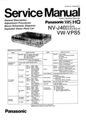
Panasonic NV-J40 Video Cassette Recorder manual available for free PDF download: Service Manual
Panasonic NV-J40 Service Manual (69 pages)
Brand:
Panasonic
| Category:
VCR
| Size: 15.03 MB
Table of Contents
Specifications
1
Contents
2
Technical Information
4
How to Install the VPS Decoder
4
Top View
4
Rear View
4
Modification for Preventing the Interference
5
Service Information
6
How to Check the Cracked Chip Part
6
How to Replace the Chip Part
6
How to Remove the Flat-IC
7
General Descriptions
8
Features
8
Auto Operation
8
Auto Play
8
Initialization of Channel Memory IC
9
Service Information Display
10
Controls and Components
11
Front
11
Digital Tracking
11
Vertical Lock Adjustment
11
Multi-Function Display
12
Rear
12
Infra-Red Remote Controller
13
Repeat Playback
13
Power Source for the Remote Controller
14
When the Bar Codes Cannot be Read
14
Cleaning
14
Adjustment Procedures
15
Disassembly Method
15
Disassembly Flow Chart
15
Detail of Disassembly Method
15
Removal of the Front Panel Unit
16
Removal of the Timer C.B.A. & Operation C.b.a.
16
Removal of the Main C.B.A. & Power Supply Unit
16
Removal of Main C.B.A.
16
Mechanical Adjustment Procedures
17
Pack Servicing Position
17
Removal of the Cassette Compartment
17
Removal of Cleaner Arm Unit
17
Location of Test Points & Controls
18
Circuit Board Layout
18
Electrical Adjustment Procedures
19
Test Equipment
19
Preparation
19
How to Read Adjustment Procedures
19
Servo Section
20
Luminance & Chrominance Section
20
PG Shifter Adjustment
20
Y-NR Balance Adjustment
20
Recording Current Adjustment
21
Video Frequency Response Adjustment
21
Audio Section
22
Timer Section
22
Bias Current Adjustment
22
Timer Reference Clock Adjustment
22
Block Diagrams & Schematic Diagrams
23
System Control & Servo Block Diagram
23
Power C.B.A.
29
System Control & Servo Schematic Diagram
30
Waveform of System Control & Servo
32
System Control & Servo Ics DV Voltage Chart
33
System Control & Servo Transistors DC Voltage Chart
33
Sub Main Schematic Diagram
34
Luminance & Chrominance Schematic Diagram
35
Main Signal Path in Rec Mode
36
Main C.B.A.
37
Main C.B.A. Address Information
38
Luminance & Chrominance Pack Schematic Diagram
39
Signal in Rec Mode
40
Signal in Playback Mode
40
Input/Output Pack Schematic Diagram
43
Input/Output Pack C.B.A.
45
Head Amp Schematic Diagram
46
Head Amp C.B.A.
47
VPS Pack, VW-VPS5 Schematic Diagram
48
TV Demodulator Pack Schematic Diagram
50
Remote Controller Schematic Diagram
59
Interconnection Schematic Diagram
61
Ics and Trs Information
62
Exploded View
63
Chassis Parts Section
64
Cassette up Mechanism Section
65
Casing Parts Section
66
Packing Parts Section
67
Remote Controller Unit
68
Advertisement
Advertisement
Related Products
Panasonic NV-J45 Series
Panasonic NV-J45A
Panasonic NV-J45EA
Panasonic NV-J40EG
Panasonic NV-J40B
Panasonic NV-J40EI
Panasonic NV-J40EO
Panasonic NV-J40EV
Panasonic NV-J40EO-W
Panasonic NV-J35EA
Panasonic Categories
Camcorder
Air Conditioner
TV
Digital Camera
Cordless Telephone
More Panasonic Manuals
Login
Sign In
OR
Sign in with Facebook
Sign in with Google
Upload manual
Upload from disk
Upload from URL