Sign In
Upload
Manuals
Brands
NEC Manuals
Telephone
NEAX 2400 ICS
NEC NEAX 2400 ICS Circuit Cards Manuals
Manuals and User Guides for NEC NEAX 2400 ICS Circuit Cards. We have
3
NEC NEAX 2400 ICS Circuit Cards manuals available for free PDF download: Features Manual, Manual, Installation Manual
NEC NEAX 2400 ICS Features Manual (572 pages)
Brand:
NEC
| Category:
Telephone
| Size: 5.17 MB
Table of Contents
Table of Contents
13
Feature List
13
Attendant Camp-On with Tone Indication
31
Attendant-Controlled Conference
34
Attendant Console
35
Attendant Keypad
39
Attendant Lockout
40
Attendant Loop Release
41
Attendant Override
43
Automatic Recall
46
A-8D Automatic Recall - D Term
48
Announcement Service
49
Alternate Routing
50
Audible Indication Control
51
Account Code
52
Attendant Night Transfer
54
Authorization Code
56
Automatic Trunk Test
59
A-29 Authorization Code - Tie Line Incoming Routes
61
Automatic/Manual Intercom
63
Account Code - Attendant
66
All Zone Paging
67
Announcement Service - Attendant
69
Attendant-To-Attendant Calling
70
Automatic Idle Return
71
Automatic Number Identification (ANI)
72
Automated Attendant
74
Answer Hold - Attendant
76
Authorization Code Display Elimination
78
Attendant Overflow
79
Add on Conference - 8 Party
81
Analog Caller ID (Class SM)
84
Analog Caller ID - Station
89
Busy Lamp Field - Flexible
90
Busy Verification
91
B-5D Boss - Secretary Override - D Term
95
Brokerage - Hotline
97
B-8 Boss - Secretary - Message Waiting Lamp Control
99
Boss - Secretary Transfer
103
Brokerage Hotline - Outside
106
Blind Transfer to Attendant
107
Blind Transfer to Station
109
Call Back
110
C-1D Call Back - D Term
112
Call Forwarding - Busy Line
115
C-2D Call Forwarding - Busy Line - D Term
119
Call Forwarding - Don't Answer
126
C-3D Call Forwarding - Don't Answer - D Term
129
Call Forwarding - All Calls
135
C-5D Call Forwarding - All Calls - D Term
137
Call Hold
142
C-6D Call Hold - D Term
145
Call Pickup - Group
148
Call Processing Indication
152
Call Queueing
153
Call Transfer - Attendant
154
Call Transfer - All Calls
156
C-11D Call Transfer - All Calls - D Term
159
Call Waiting - Terminating
162
Call Waiting Lamp
165
CCSA Access
166
Class of Service - Individual
167
Consultation Hold - All Calls
169
C-17D Consultation Hold - All Calls - D Term
171
Centralized Attendant Service (CAS)
173
Code Calling Access
177
C-22D
178
Called Station Status Display - D Term
178
C-24D
180
Calling Number Display - D Term
180
Call Forwarding-Intercept / Announcement
181
Call Forwarding - Override
183
C-27D Call Waiting - Answer - D Term
185
Call Forwarding - All Calls - Outside
187
Call Park
190
Call Pickup - Direct
192
Call Waiting - Originating
193
Consecutive Dialing - Attendant
196
Called Number Display - Attendant
197
Call Forwarding - Busy Line - Outside
198
Consecutive Speed Calling - System
201
Call Forwarding - All Calls - Announcement
202
Call Back - Delayed
204
Call Forwarding - Don't Answer - Outside
205
Call Forwarding - Intercept/Announcement - Attendant
208
Call Waiting Lamp - UCD
209
Call Forwarding - I'M here
210
Centrex Compatibility
211
C-133 Call Forwarding - Don't Answer to UCD Queue
212
Call Hold - Conference
213
Call Block
215
Call Return
216
Call Hold Pick up
220
Dial Access to Attendant
221
Dictation Access
222
Digital Display - Station
224
Digital Display - Trunk
226
Direct-In Termination (DIT)
228
Direct Inward Dialing (DID)
230
Direct Outward Dialing (DOD)
232
Distinctive Ringing
233
D-11D
235
Do Not Disturb - D
235
D-13D
237
Dial Monitor - D Term
237
Day/Night Class of Service
238
Direct Digital Interface
241
Delay Announcement - UCD
244
D-32D Dual Hold - D Term
246
Dial Intercom
248
D-90D
254
Delayed Ringing - D Term
254
Delay Announcement - Attendant
257
Direct Station Selection (DSS) Console
261
Distinctive Ringing - Caller ID
263
Executive Right-Of-Way
265
E-1D Executive Right-Of-Way - D Term
268
E-3D Elapsed Time Display - D Term
269
E-4D Exclusive Hold - D Term
270
Emergency Call
271
E911-ANI Unified Number of Digits
273
Flexible Numbering of Stations
275
FX Access
276
F-3D
278
Flash Button - D
278
Flash Entry - D
279
Faulty Trunk Report
282
Forced Account Code
283
Flexible Assignment of Function Buttons
285
Follow Phone
286
Group Calling
290
Hotline
292
House Phone
293
H-4D Hands-Free Answer Back - D Term
294
H-5D Hands-Free Dialing/Monitoring - D Term
295
Hotline - Outside
296
Immediate Ringing
297
Incoming Call Identification
298
Incoming Central Office Call to Tie-Line Connection
299
Individual Trunk Access
301
Inter-Position Transfer
302
Individual Attendant Access
303
I-7D I-Hold Indication - D Term
304
I-8D I-Use Indication - D Term
305
Intercom Calling
306
I-10D
308
Inter-Office Off-Hook Queuing
309
Immediate Ringback Tone
310
Internal Zone Paging
311
Lamp Check
313
Line Lockout
314
Least Cost Routing - 3/6-Digit
316
Last Number Called - Single-Line Station
319
L-6D Last Number Called - D Term
320
Line Reconnect - same Line - D
325
Line Reconnect - Other Line D
326
L-9D Line Pre-Selection - D Term
327
LCR - Time of Day Routing
328
Line Load Control
329
Line Load Control - Automatic
330
Line Load Control - MAT
331
Listed Directory Number
332
LDN Night Connection
333
LDN Night Connection - Outside
335
Meet-Me Paging
336
Miscellaneous Trunk Access
338
Miscellaneous Trunk Restriction
339
Multiple Console Operation
341
Music on Hold
343
Meet-Me Paging - Attendant
344
Maintenance Printout
347
Maintenance Administration Terminal (MAT)
348
Message Reminder
351
M-19D
353
Message Reminder - D
353
Term Term
353
Multiple Line Operation - D
356
Message Waiting Lamp Setting - Attendant
357
Multiple Call Forwarding - Busy Line
359
Multiple Call Forwarding - Don't Answer
365
Message Center Interface
369
Message Waiting Lamp Setting - Station
372
Multiple Call Forwarding - All Calls
376
Manual Signaling
381
Multi Channel Recording - DAT
382
MF Signaling - DID
397
M-85D Message Waiting Indication - D Term
399
MF ANI to SMDR
400
Night Connection - Fixed
401
Night Connection - Flexible
403
Non-Delay Operation
404
N-7D Non-Exclusive Hold - D Term
405
N-8D Non-Square Line Assignment - D Term
407
Night Connection Outside - System
408
Name Display - System
409
On-Line Maintenance
413
Outgoing Trunk Queuing
414
Off-Hook Alarm
418
Off-Hook Queueing
420
Overflow - UCD
422
Outgoing Trunk Queuing - Attendant
424
Outgoing Trunk Busy Announcements
425
Paging Access
430
Passing Dial Tone
432
Power Failure Transfer
434
Pushbutton Calling
435
Pushbutton Calling - Attendant Only
436
Pushbutton to Rotary Conversion
437
Peg Count
438
Priority Call
440
Paging Transfer
442
Periodic Time Indication Tone
444
Prime Line Pickup - D
445
Term
445
Privacy - D Term
446
Term
449
Privacy Release
449
Priority Paging
455
Pad Lock
457
Personal Ringer
458
Remote Access to System
459
Reserve Power
461
Restriction from Outgoing Calls
462
Rotary Dial Calling
464
Route Advance
465
Remote Maintenance
467
Radio Paging
469
Route Restriction - Announcement
471
Rs-464A Pad
472
Ringer Mute
476
Single-Digit Station Calling
477
Special Dial Tone
478
Speed Calling - System
479
S-3D Speed Calling - System - D Term
481
Splitting
483
S-4D Splitting - D Term
484
Station-Controlled Conference
485
Station Hunting - Circular
486
Station Hunting - Secretarial
489
Station Hunting - Terminal
490
Station Message Detail Recording (SMDR)
494
Station-To-Station Calling
498
S-12 Station-To-Station Calling - Operator Assistance
499
Step Call
500
Serial Call
501
Single-Digit Feature Code
503
Speed Calling - Station
504
Speed Calling - Group
506
S-24D Save and Repeat - D Term
508
S-25D
509
Service Display - D Term
509
Term
510
Service Feature Peg Count
512
Software Line Appearance
514
Speed Calling Override - System
516
Station 5Db PAD
518
Serial Call - Loop Release
519
Split Call Forwarding
520
Slumber Time - Do Not Disturb
528
Serial Call - D Term
530
SMDR Output Expansion - ANI/CPN
533
Tandem Switching of TIE Trunks - 2/4-Wire
535
Three-Way Calling
537
T-2D Three-Way Calling - D Term
540
TIE Line Access
541
TIE Line Connection with Pad Control
543
Toll Denial/Toll Diversion
544
Toll Restriction - 3/6-Digit
545
Trunk Answer from any Station (TAS)
546
Trunk Group Busy Lamp
548
Trunk-To-Trunk Connection
549
Tenant Service
550
Time Display
552
T-18D
553
Time Display - D Term
553
Trunk Line Appearance
554
Trunk-To-Trunk Third-Party Cancellation
556
Timed Reminder
557
Uniform Call Distribution (UCD)
559
Universal Sender
564
Variable Timing Parameters
565
Voice Call
568
V-2D Voice Call - D Term
569
V-3D Volume Control - D Term
571
WATS Access
572
Advertisement
NEC NEAX 2400 ICS Manual (149 pages)
Digital Remote Unit System
Brand:
NEC
| Category:
Control Unit
| Size: 1.22 MB
Table of Contents
Table of Contents
4
Chapter 1 Introduction
12
Chapter 2 General Information for Dru
12
Table 1-1 Configuration of the DRU System Manual
12
Procedure
13
Table 1-2 Related Reference Manuals
13
Figure 2-1 Outline of NEAX2400 IMS When the DRU Is Used
14
General
14
Features of the DRU
15
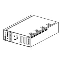
Figure 2-2 Outer View of the DRU
16
Figure 2-3 Example of Installation of the DRU (Wall Mounting)
17
How to Install the DRU
17
Figure 2-4 Example of Installation of the DRU (Floor Installation Using STAND ASSEM) (Option)
18
Figure 2-5 Example of Installation of the DRU (Mounting on the 19-Inch Rack) (Option)
19
Table 2-1 Specifications of the DRU
20
Table 2-2 Specifications of Interface between NEAX2400 IMS and the DRU
20
Circuit Cards in the DRU
21
Figure 2-6 Outer View of DRE Card in DRU-30-A
21
Table 2-3 DRE Card Lamp Indication Reference Table
23
Batteries (Option)
24
Table 2-4 Specifications of the Battery
24
Figure 2-9 Mounting Location of DLI Card
25
Functions of Circuit Cards for the DRU
25
Figure 2-10 Front View of PA-DAIA
26
Table 2-5 PA-DAIA Lamp Indication Reference Table
27
Figure 2-11 Front View of PA-DAIC
29
Table 2-6 PA-DAIC Lamp Indication Reference Table
30
Figure 2-12 Mounting Location of 2DLI Card
31
Figure 2-13 Front View of PA-2DAID
32
Table 2-7 PA-2DAID Lamp Indication Reference Table
33
Table 2-8 Relationship between each Circuit on the DLI and LENS
34
Figure 2-14 Local Loop-Back Check
36
Loop-Back Function Test
36
Figure 2-15 Remote Loop-Back Check
37
Figure 2-16 Remote Loop-Back
38
Figure 3-1 Static Caution Indication
39
Chapter 3 Installation Procedure
39
Figure 3-2 3M Model 8012 Portable Field Service Kit
40
Installation Procedure
41
Figure 3-3 Marking for Mounting the DRU on the Wall
42
Marking and Drilling
42
Figure 3-4 Drilling for Mounting the DRU on the Concrete Wall
43
Figure 3-5 Drilling for Mounting the DRU on the Wooden Wall
43
Figure 3-6 Marking for the STAND ASSEM
44
Figure 3-7 Drilling for Setting the STAND ASSEM
45
Figure 3-8 Fastening of the STAND ASSEM
46
Figure 3-9 Remove the DRU Cover
47
Installation of the DRU
47
Figure 3-10 Installation of the DRU (Wall Mounting)
48
Figure 3-11 Installation of the DRU (Floor Installation by the STAND ASSEM)
49
Figure 3-12 Installation of the DRU (When Mounting 4 Sets of DRU Onto the 19-Inch Rack)
50
When Mounting the DRU on the 19-Inch Rack (Option)
50
Figure 3-13 Installation of the DRU (When Mounting 3 Sets of DRU Onto the 19-Inch Rack)
51
Figure 3-14 Confirmation of Short Piece
52
Confirmation of Power Cable of the DRU
52
Figure 3-15 Battery Connection (When Mounting the Battery Within the DRU)
53
Figure 3-16 Battery Cable Connection (When Mounting the Battery Within the DRU)
54
Figure 3-17 Battery Mounting
55
When Mounting the Battery Externally
55
Figure 3-18 Battery Cable Connection (When Mounting the Battery Externally)
56
Switch Setting of the DRE Card
57
Switch Setting Sheet of DRE Card in DRU-30-A
58
Figure 3-19 Circuit Card Mounting (Partial Insertion)
78
Figure 3-20 Connection of DRU
103
Figure 3-21 "LT" Connector Pin Accommodation for the DLI Mounted in PIMA
104
Figure 3-22 "LT" Connector Pin Accommodation for the DLI Mounted in PIMB
105
Figure 3-24 Connection of Digital Interface for IMG (ICS)
109
Figure 3-25 Connection of Digital Interface for MMG (ICS)
110
Figure 3-26 Connection of Analog PB TEL/D Term
111
Figure 3-27 Details of Analog PB TEL Connection
112
Figure 3-28 Details of D Term Connection
113
Figure 3-29 "CHAMP" Connector Pin Accommodation for DRU-30-A/DRU-30-S3
114
Figure 3-30 Connection of D Term
115
Cleaning and Visual Inspection
117
Chapter 4 Installation Test Procedure
118
Start-Up of the DRU
119
Check of Lamp Indications and System Messages
120
Check of Loop-Back Test Execution Required/Not Required
121
Check of Battery Operation When Power Supply Failure to the DRU
122
Figure 4-1 Mounting of the DRU Cover
123
Chapter 5 Maintenance Procedure
124
Table 5-1 System Messages for the DRU
125
Technical Terms for Explaining Message Detail Data
125
Circuit Card Location Information
126
Figure 5-1 Relation between Accommodated Location Information and Mounting Location
126
How to Proceed with Diagnostic Work from System Message
129
Figure 5-2 Example of Diagnostic Work Items and Symbols
130
System Messages
131
Fault Diagnosis by Loop-Back Test
133
Procedure for Loop-Back Diagnosis from the DLI to the DRU
138
Loop-Back Diagnosis between the DLI and the Transmission Equipment
140
Transmission Equipment
141
Loop-Back Diagnosis between the DRU and the Transmission Equipment
143
Transmission Equipment
144
Fault Repair Procedure
146
DRU Fault
147
Battery Fault
148
NEC NEAX 2400 ICS Installation Manual (32 pages)
Brand:
NEC
| Category:
PBX
| Size: 0.41 MB
Table of Contents
Table of Contents
3
Chapter 1 General
7
Outline
7
Outer View of CPR
7
Sn1433 Cpraf-A/Sn1435 Cprah-A
8
Internal Cable Connection
9
Switch Setting on CPU Board
10
Jumper Switch Setting on CPU Board
10
Chapter 2 Installation Procedure
11
Mounting of CPR
11
Mounting of HFD
12
Cable Connection for IMG X
13
Locations of Connectors (IMG X )
13
Cable Connections for IMG X
14
IMG Dxh
16
Locations of Connectors (IMG Dxh )
16
Cable Connection
17
Cable Connections for IMG Dxh
17
Mounting of Additional GATE (PZ-GT19) Card
19
Removal of CPR
19
Removal of CPR Cover
20
Removal of Slot Cover
21
Mounting of GATE Card
22
Chapter 3 System Startup
23
EMA Card Mounting Location
23
Lamps and Switches on EMA Card Operation Panel
23
Operation Panel
24
Program Installation
25
Off-Line Startup
25
HD Initialization
26
Basic Software Installation
27
Standard Service Software Installation
28
Lamp Indication and System Message
29
OPE/ACT Lamp Indication
30
Advertisement
Advertisement
Related Products
NEC NEAX 2400 IPX
NEC NEAX 2000IVS Dterm E Series
NEC NEAX2400IPX
NEC NEAX7400 ICS M120e
NEC NEAX 1400 IMS
NEC NEAX1400 IMS
NEC NDK 900
NEC NVM-CA Series
NEC NVM-22CA
NEC NVM-202exCA
NEC Categories
Monitor
Projector
Server
Telephone
Computer Hardware
More NEC Manuals
Login
Sign In
OR
Sign in with Facebook
Sign in with Google
Upload manual
Upload from disk
Upload from URL