Sign In
Upload
Manuals
Brands
Motorola Manuals
Measuring Instruments
R-20010
Motorola R-20010 Manuals
Manuals and User Guides for Motorola R-20010. We have
1
Motorola R-20010 manual available for free PDF download: Maintenance Manual
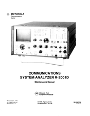
Motorola R-20010 Maintenance Manual (519 pages)
COMMUNICATIONS SYSTEM ANALYZER
Brand:
Motorola
| Category:
Measuring Instruments
| Size: 84.11 MB
Table of Contents
Table of Contents
2
Paragraph Page
3
Foreword
14
Repair Request Form
17
Section 1. Introduction
18
Description
18
Physical Characteristics
18
Electrical Characteristics
18
Input/Output Characteristics
24
Major Assemblies
25
System Analyzer - Top View
26
System Theory of Operation
27
Description
27
System Control
27
Processor
27
Processor Bus
27
General
27
Generate Mode
29
RF BUS Control
29
MOD Control
29
Receiver Control
29
Duplex Control
29
Receiver Filters
29
Frequency Standard
30
RF Synthesizer
30
Wideband Amplifier
30
Step Attenuator
30
Input/Output
30
Wattmeter
30
Monitor Mode
31
RF Input
31
2.5.3 Recei Ver
31
Duplex Generator (Standard and Enhanced)
32
Code Synthesizer
32
Frequency Counter
33
Digital Voltmeter (DVM)
33
Distortion/Sinad Meter
34
Oscilloscope
34
SYSTEM ANALYZER Block Diagram
36
Alignment Procedure
45
Introduction
45
Test Equipment Required
45
Preparation for Alignment
45
Basic Alignment Procedure
45
CRT Intensity Bias
45
CRT Astigmatism and Geometry
47
CRT Vertical Centering and Trace Rotation
47
3.2.7 Crt Horizontal Gain
47
Alignment Points
47
3.2.8 Crt Vertical Gain
48
Vertical Input Gain
48
DVM Zero
49
Character Generator
49
Spectrum Analyzer Centering
49
Alignment Points
49
3.2.13 Horizontal Timebase
50
RF Synthesizer Module (A9)
55
Alignment Points
58
System Checkout and Troubleshooting
69
System Checkout and Troubleshooting Procedures
70
Battery Charger Board
79
Test-Point Identification
79
Frequency Standard
80
System Wirelist and Parts List- System Motherboard (A19)
80
System Motherboard Wirelist
88
System Wirelist
158
Communications
181
High-Voltage Power Supply (A1)
184
Scope Amplifier Board
193
Printed Wiring Board Assembly and Parts List
202
High Voltage Power
206
Control Logic Functions
207
Battery Charger Board (A3)
208
Switcher Board (A6)
208
Output Voltages
208
Control Board (A4)
217
Block Diagram
217
Control Board (A4)
221
Control Board (A4)
223
Output Board
225
Printed Wiring
229
Internal DVM Inputs
234
Scope/DVM Control Board {A7)
237
Block Diagram
238
Scope/DVM Control Board (A7)
244
Control Board (A7)
247
Figure
247
Printed Wiring Board Assembly
247
Description
249
Theory of Operation
249
Linear if Section
249
Logarithmic Amplifier
250
0.2.3 FM/SSB/WB Signal-Present Detectors
251
0.2.4 Baseband Audio-Processing Circuits
252
Baseband Audio-Processing Circuits
252
Digital Control and Power Conditioning
252
Low-Pass Filter-Control-Bit Patterns
253
High-Pass Filter-Control-Bit Patterns
253
Modulation-Select-Control-Bit Patterns
253
Receiver Board (AS)
254
Logarithmic Amplifier
254
Section 11. Rf Synthesizer Module (A9)
275
11.1 Description
275
Theoryofoperation
275
Reference and Control Board (A9A 1)
275
Receiver Board
275
Reference and
275
Synthesizer Output
275
640-Mhz Loop Board (A9A6)
275
Printed Wiring Board Assembly
276
Ghz Loop Board
277
Mhz Loop
277
640-Mhz Loop Board (A9A6)
278
Printed Wiring
279
Block Diagram
280
RF Synthesizer Module
285
Printed Wiring Board Assembly
285
And Parts List
285
To 440-Mhz Loop Board (A9A2)
286
Oscilloscope
287
To 440-Mhz Loop
287
To 440-Mhz Loop
290
310 TO 440-Mhz LOOP BOARD
291
Synthesizer Output Board
292
Schematic
293
Mhz LOOP BOARD (A9A4)
299
Schematic
299
Schematic
302
Mhz Loop Board (A9A4)
304
Ghz Loop Board (A9A5)
307
Ghz Loop Board (A9A5)
310
Board
311
640-Mhz Loop Board (A9A6)
314
640-Mhz Loop Board (A9A6)
317
Synthesizer Motherboard (A9A7)
320
Assembly and Parts List
320
Printed Wiring
320
Audio Synthesizer Board (A10)
323
Description
323
Theory of Operation
323
Audio Synthesizer
323
DPL Generator
323
Assembly and Parts
323
1-Khz Tone
324
Internal Modulation
324
External Modulation
324
Modulation Control
324
Audio Synthesizer Board (A10)
327
Processor Interface Board (A11)
336
Assembly and Parts
336
Board Control
338
Processor Interface Board (A11)
340
Section 13. Processor Interface Board (A11)
345
Board
348
Printed Wiring Board Assembly and Parts List
348
Printed Wiring Board Assembly
348
Description
350
Theoryofoperation
350
Microprocessor
350
Memory
350
Memory Map
350
14.2.3 Input/Output
351
Memory Map
352
14-3. Block Diagram
355
Printed Wiring Board Assembly
362
Block Diagram
365
01-P29050H001
372
Description
376
Microprocessor
376
Front-Panel Interface Board (A15)
376
Printed Wiring
376
AF ADD and DATA BUS
377
Input Switching
378
RF-Attenuator Encoding
378
Functions of Miscellaneous Inputs
379
Sweep-Select Encoding
379
Block Diagram
381
Printed Wiring Board Assembly and Parts List
385
Front-Panel Interface Board (A15)
385
Theory of Operation
387
Frequency-Standard Interface Board (A16)
387
16.1 Description
387
Internal Source
387
External Source
387
Printed Wiring
387
Frequency-Standard Interface Board (A16)
390
Wattmeter Board
393
Wideband Amplifier Board
394
Wide Band Amplifier Board
394
Assembly and Parts
394
Wide Band Amplifier
394
Duplex Generator Board (a 17 A3)
395
Duplex Generator Board
395
Generator Board
397
Board
398
Wattmeter
404
Section 17. Rf Input Module (A17)
405
RF Wattmeter Board
410
Wideband Amplifier
411
RF Input Module
411
Wideband Amplifier Board (A17A2)
416
Duplex Generator Board (A17A3)
419
Enhanced Duplex Generator
425
RF Input Module
430
Enhanced Duplex Generator Board (A1 7A3)
432
Front Panel Assembly (A18)
434
Description
434
CONTROLS, SWITCHES and Leos
434
Front-Panel
434
Inside Front Panel
442
Inside Front Panel
443
Switch Interconnect Board (A18A2)
447
Section 19. Battery Assembly
451
19.1 Description
451
Installation
451
Printed Wiring
451
19.3 Operation
452
Section 20. Cellular Telephone Test Option
455
20.1 Description
455
Theory of Operation
455
Transmitted Data
455
Received Data
455
Control
455
Modulation
455
Manual-Mode Control
455
Block Diagram
457
Cellular Telephone Test Option
457
Part 1. Ieee Interface
466
21 .1 Description
466
Theory of Operation
466
IEEE Bus Interface
466
Remote Interface
466
Assembly and Parts List
466
IEEE Bus Interface
467
RF-Level Control
467
Modulation Control
467
Multipurpose Input/Output and Relay Ports
467
21.3 Description
467
21.4 Theory of Operation
467
Bus Interface
467
Address-Decode and Control-Latch Circuitry
467
Assembly and Parts List
467
Block Diagram
467
Printed Wiring Board
475
Section 22. Secure Com Option
488
Description
488
22.2 Theory of Operation
488
Transmit
488
Receive
488
Encoder Section
488
Inputs
488
Encryption Type
488
Encoder Outputs
488
SECTION SECURE COM OPTION (Cont)
488
Measurements
489
22.6.1 Bit Error Rate Test
489
Deviation Measurement
489
Duplex Generator
489
Oscilloscope Displays
490
Features
490
Self Testing
490
22.7 .3 Dual Code Operation
490
22.7.4 Plain Text Output
491
22.7.5 Printer Interface
491
Block Diagram
493
Block Diagram
507
Advertisement
Advertisement
Related Products
Motorola R-20018
Motorola R-20028
Motorola R-2002A
Motorola R-2001A
Motorola R-2001D
Motorola R2010D
Motorola R2008D
Motorola R2008C
Motorola R2001C
Motorola R-2600
Motorola Categories
Cell Phone
Two-Way Radio
Baby Monitor
Cordless Telephone
Radio
More Motorola Manuals
Login
Sign In
OR
Sign in with Facebook
Sign in with Google
Upload manual
Upload from disk
Upload from URL